Documentation
Apartment house with 13 parties and underground car park
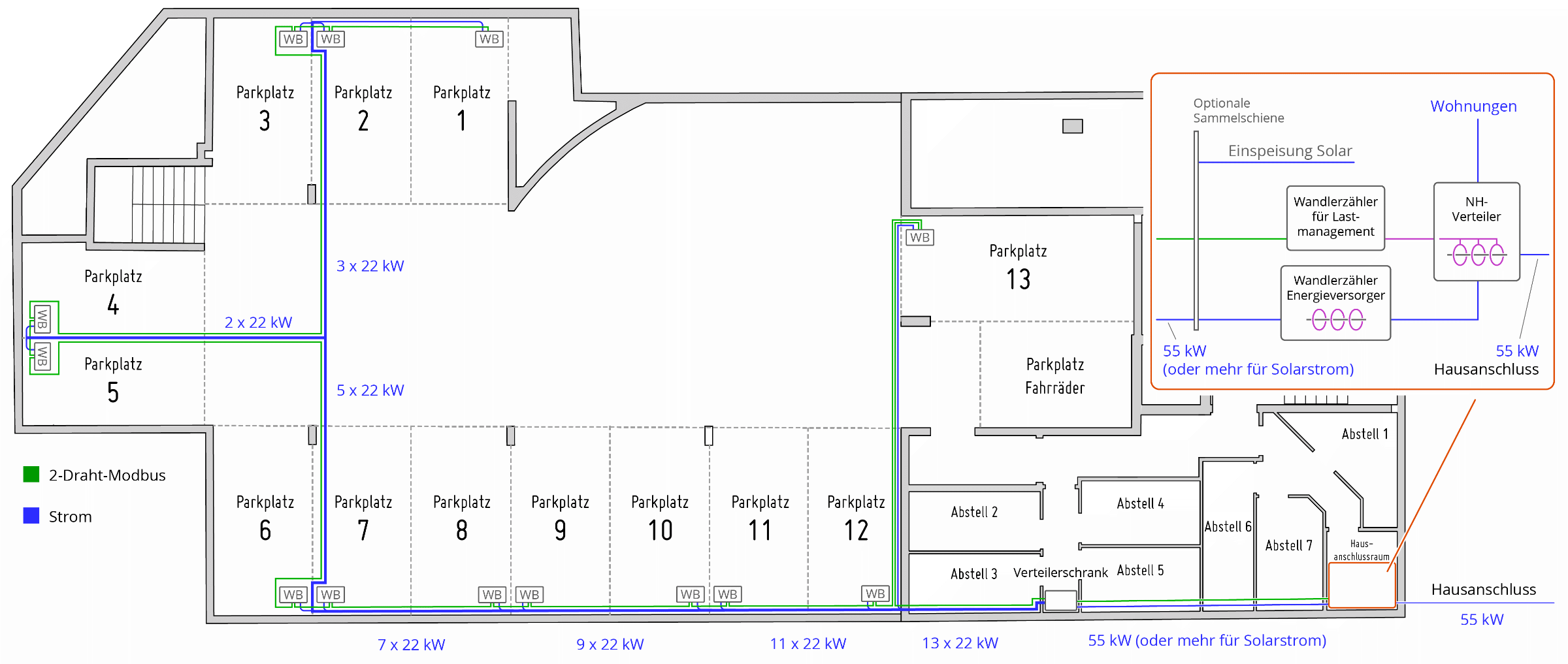
13 EVSEs of 22kW each connected to the busbar. This means that 55kW house connection power plus up to 52kW photovoltaic power minus the house consumption of all flats / general electricity is available. Thus, the underground garage can draw a maximum of 55kW plus 52kW, i.e. the supply cable for the distribution cabinet is designed for a good 125kW. A load measurement by the energy supplier in the house showed that the house predominantly draws a power of 1.5kW to 5kW. Only at peak times (approx. 16-19 o'clock) can a power demand of approx. 20kW arise. Therefore, no increase in the house connection value and associated costs was necessary.
The distribution cabinet contains a circuit breaker and a type A RCD for each EVSE. The EVSEs have integrated DC fault protection, which is why more expensive RCDs are not necessary. The EVSEs are wired in a star configuration.
A central bidirectional grid reference meter at the house connection point measures the load of the house connection. This is an ABB B24 transformer meter (Modbus) with transformer coils in a NH distributor. Alternatively, an Eastron SDM630 MCT could be used. This way, the cFos Charging Manager sees the consumption of all flats, as well as the feed-in of the solar system, and can regulate the charging power down during peak times.
For each EVSE there is a calibrated ABB B23 meter (Modbus) for billing purposes and to determine the phase usage of the charging electric cars. Alternatively, Eastron SDM72DM-V2, Orno WE 516/517 or YTL DTS353F-2 could be used. The meters are installed in the EVSEs, but could also be installed in the distribution cabinet.
Every year, the meter readings are read in the web interface of the cFos Charging Manager and the service charge statement is created for the car park tenants. Users can read the meter display on site at any time. In the cFos Charging Manager, the administrator can download a log file of all transactions as a CSV file, which can then be further processed with Excel, for example. Optionally, there is also a transaction log per user. For each charging process, the start and end time, charged kWh, total consumption and the RFID of the user are logged.
Load management takes place via the cFos Charging Manager on a Raspberry PI. All EVSEs are cFos 22kW EVSEs connected via two-wire (Modbus RTU). Alternatively or in a mixed configuration, ABL eMH1, Heidelberg Energy Control or EVSE with the EVRacing WB DIN Modbus controller (e.g. Stark in Strom) could also be used. A mixed configuration of these devices is also possible.
The Raspberry PI is connected to the internet via the router in the house. Alternatively, it could also be connected to an LTE router. There are 2 modbus adapters on the Raspberry, with which 2 separate modbuses can be realised. Because of the cable lengths of approx. 60m, twisted cables (e.g. wire pairs of Cat5 or Cat7 cables) and terminating resistors at the bus ends are recommended. To protect the Raspberry, the RS-485 adapters are operated with USB isolators. All meters (1x ABB B24 + 13x ABB B23) are located on bus 1, all cFos Power Brain wallboxes are located on bus 2.
Parallel to the two Modbus RTU connections, you could also lay LAN to all parking spaces and then use EVSEs that are operated with OCPP or Modbus TCP, such as ABB Terra AC 22, ABL eMH2, Innogy eBox Professional, Keba KeContact P30 c- or x-series, Webasto Live, Mennekes Amtron, Wallbe Eco. With additional WLAN coverage using WLAN access points, the cFos Power Brain Wallboxs could also be connected in Modbus TCP mode, as well as other EVSEs with WLAN, such as go-e charger. Here, a reserve WLAN access point was installed in the garage to simplify software updates of the cFos Power Brain Wallboxs.
For charging authorisation, a second Raspberry PI with USB RFID reader for 13.56Mhz Mifare cards is installed at the entrance to the underground car park. This allows EVSEs to be operated that do not have an RFID reader. 13.56 Mhz is practical because many "cheque cards" that you have with you anyway support this standard (except EC and credit cards). But you could also use an RFID reader with 125 kHz (this is often used in connection with alarm systems). The cFos Charging Manager takes into account the RFID transmitted by the EVSE, so a central reader is not absolutely necessary.
In the event of a load management failure, a 3-minute fail-safe timer is activated on all cFos Power Brain Wallboxs, i.e. the EVSEs switch to the minimum charging current after 3 minutes of communication failure so that no fuses are triggered in the event of a failure.
Configuration of the cFos Charging Manager
Max. Total power (W): 55000 Power reserve (W): 5000 This is subtracted from the 55kW as a control reserve Max. Total EVSE power (W): 125000 This corresponds to the strength of the line from the busbar to the garage. It is desired to use the peak power of the solar system for charging in addition to the house connection power, which is why the line was dimensioned in this way. The cFos Charging Manager therefore ensures that neither the house connection nor this supply line is overbooked.
USB1 of the Raspberry PI has the Modbus RTU cabling of the EVSE. This means that COM1 is entered here as the address. Since the cFos Power Brain Wallboxs are set to 9600 baud, 8 data bits, no parity and 1 stop bit, the address for all is COM1,9600,8,n,1. A separate Modbus ID must be assigned for each EVSE. For simplicity, the Modbus ID is equal to the parking space number: 1,2,3,...The same COM parameters and the Modbus IDs are entered in the respective EVSE. The load management of the EVSE is deactivated, as it is taken over by the Raspberry here. In the cFos Charging Manager on the Raspberry, enter the same Modbus IDs accordingly and "cFos Power Brain" as the device type.
USB2 of the Raspberry PI has the wiring of the ABB B23 meters and the ABB B24 transformer meter. Here, 9600,8,n,1 is also set in the display of the meters and the parking space number is assigned as the Modbus ID. There can be no collision of Modbus IDs with the EVSEs, as these are located on the other bus. The ABB B24 is also set to 9600,8,n,1 and the Modbus ID is 100. This must be set both in the meters and in the cFos Charging Manager, i.e. the address is COM2,9600,8,n,1 and the Modbus ID is 1,2,3,... and 100. select "ABB B23/24" as the device type. All ABB B23 meters are assigned the role "E-car consumption" and the ABB B24 the role "Mains supply", since it is installed at the mains transfer point.
Now all ABB B23 meters must be pinned to the EVSE in the configuration UI of the matching EVSE so that the cFos Charging Manager knows which meter belongs to which EVSE.
The cFos Charging Manager can query both buses in parallel, but can only poll all devices per bus one after the other. It is therefore better to limit yourself to 15-20 devices per bus and, if necessary, to connect further buses to the Raspberry using a USB RS-485 adapter.
Since individual cars may charge in single-phase or two-phase mode, all EVSEs should be installed with a phase rotation of 120 degrees to each other. This phase rotation can be communicated to the cFos Power Brain Wallbox in the respective EVSE setting. This enables the Charging Manager to detect phase imbalances and limit the charging current. It can also take into account, for the benefit of the charging cars, if several single-phase cars are charging on different phases (in relation to the house connection).
Since meters are used for all EVSEs that output the currents of individual phases separately, the phase utilisation of the EVSEs can be set to "Determine", which provides optimum utilisation of the available power.
In order to be able to see certain powers in the web interface at a glance, the following "software meters" were configured in the cFos Charging Manager with the "Display" role: A virtual meter for the available charging power "Power avail. for EVSEs" a virtual meter for the actually used charging power "Consumed EVSE Power"
In addition, the solar system is integrated, which is actually not necessary, as there is a grid reference meter: the inverters of the solar system as a meter (here SMA Sunny Tripower) a virtual meter for the sum of the solar power "Produced Power"
Here is an overview of the different types of meters.
Costs for charging points: As cFos Power Brain wallboxes were used, all charging points are free of charge. For charging points with other wallboxes, a licence is required for each charging point. Available here in our shop. There are no further "subscription" fees.
Note: A single cFos Power Brain Wallbox can operate up to 25 devices as cFos Charging Manager. In such cases, a Raspberry Pi is not necessary.