Documentation
Configuration
In the top right-hand corner of the start page is the cogwheel symbol for configuration. Clicking on it opens a panel in which various settings can be made:
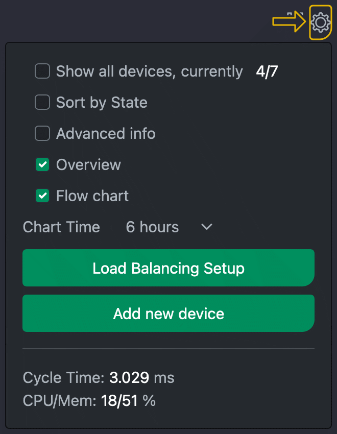
- Show all devices
Ignore visibility settings in the configuration of the individual devices - Sort by status
- Show extended information
in the device tile - Show overview
Show devices as a table under the dashboard - Show daily prices
Show the energy provider's prices in the overview diagram. In contrast to the other values in the overview diagram, these refer to the current day, i.e. the present and future. - Flow chart
Switch between flow chart and pie chart to display the available consumers and generators - Diagram time
Displayed time period of the tile diagrams - Load management setup
Set basic configuration and load management - Add new device
Display dialogue for adding new devices
Advanced options

In the following dialogues, it is possible to make additional settings by selecting the "Advanced options" checkbox. These advanced options are indicated in the description by a yellow bar on the left-hand side.

First you should enter global parameters.
| Title | The title of your project |
| Description | Here you can enter a short description of your project. |
| The title and description are displayed accordingly in the overview. | |
| Load Balancing | Activate load management. Note on the cFos Power Brain Wallbox: If you operate the wallbox standalone or as a master, activate load management. This will also allow you to use all the extended functions. If you are operating the wallbox with a different load management system or as a slave, deactivate load management (mode: Observe). |
| Max. Total current per phase (mA) | Determines the maximum available electricity that the house connection can provide. This current is available to the house, including all consumers and charging stations. You can either enter a fixed value or a formula here. This allows you to make the available house connection current dependent on switching inputs (e.g. for a ripple control receiver) or Charging Manager variables (which can be set externally via HTTP API). |
| Current reserve (mA) | Power reserve that the control system attempts to reserve. You must dimension the value so that load peaks do not cause the fuses to trip. The less information is available about the utilisation of the individual phases (via suitable meters), the higher the reserve should be selected. |
| Overdraft | In the "Overdraft" field, the Charging Manager enters the maximum value of the overdraft in milliamperes that has been seen so far and exceeds the reserve. This allows you to see later how well the regulation is working and whether you should set more power reserve. Ideally, the overdraft should be and remain 0. You can set this historical value back to 0. If the cFos Charging Manager detects an overdraw (this can be lower than the historical maximum), it reduces the available charging current by the overdraw current for 5 minutes to allow the fuse to cool down. This is displayed in red on the dashboard as an overdraw. |
| Share of total electricity (%) | This can be used to temporarily reduce the usable portion of the maximum total current. This value is not saved. |
| Max. Total wallbox current (mA) | Depending on the house installation, an additional power line may have been laid for the charging stations exclusively for charging electric cars. "Max. Total wallbox current" determines the maximum current of this line. |
| System voltage | This should normally read 230V. |
| Max. Phase imbalance (mA) | The maximum phase shift load permitted by the energy supplier (i.e. one-sided phase utilisation, e.g. for single-phase charging cars). The prescribed value is 4600 W, i.e. 20 A. Your energy supplier may allow you a higher unbalanced load. |
| Skew incl. consumption | Activated: The imbalance is calculated including all consumers and producers. Deactivated: The imbalance is only related to the charging cars. |
| Duration of a charging pause (s) | Minimum length of a break. This is important to protect devices and avoid fluctuations. |
| Delay for switching to 3-phase (s) | Time in which sufficient power must be available for 3-phase charging before switching over. |
| Reduce charging power in the event of a COM error | If the wallbox cannot be reached for more than 3 minutes, its last known charging power is counted as an external load and deducted from the total power available for charging. |
| For device deactivation | How should a device be set (if possible) if the cFos Charging Manager gives up control of it? Options: Deactivate charging, minimum charging current, cancel all limits (corresponds to OCPP free charging). |
| Energy provider | Here you can select the energy provider used for price-based charging rules. For Tibber, you also need an OAuth2 token on the configuration page. |
| Base price in cent | Here you can enter a basic price that is added to each kWh consumed. |
| Price multiplier | Here you can enter a multiplier by which the price per kWh is multiplied. The base price is then added. |
| Formula for solar surplus | Here you can enter a formula that calculates the PV surplus instead of the Charging Manager's standard calculation. Note: You can use CM._org_surplus to determine which value the Charging Manager would have used as the PV surplus. |
| Smoothing for solar surplus | You can enter a value from 0 to 1 here, 0 = no smoothing. In rare cases, counter values are so delayed that the solar surplus oscillates. You can then experiment here with values greater than 0. The higher the value, the more smoothing. In such a case, you must try out how strong the smoothing should be in your case. |
| Start transaction by loading instead of plugging in | Normally, charging processes / transactions begin when the car is plugged in and end when it is unplugged. Alternatively, you can start and end them by starting and ending charging. |
| Max. Feed-in in W | Maximum feed-in power of the generators, e.g. inverters. Must be activated for the inverter and the inverter must support this power limitation. |
| Control factor feed-in | Typically close to 1.0 to avoid oscillations when reducing the power of the inverters. |
| Feed-in tariff per kWh | Feed-in tariff in euros. |
| Grid charges in euro cent | Here you can set the grid charges due per kWh per hour. |
| OCPP Server TLS | Enable, disable or auto detect TLS |
| OCPP Server Port | TCP/IP port of the OCPP server in the cFos Charging Manager |
| OCPP Server Password | Password for logging on to the OCPP server |
| Use own certificates | If activated, an SSL certificate that you can upload under Configuration is used. If deactivated, a self-signed standard certificate is used. |
| Authorisation cache | If activated, loading is authorised using the last successfully used RFIDs if the OCPP backend cannot be reached. |
| Charging Manager variables and Charging Manager outputs | You can create your own variables here and/or have these variables managed via the HTTP API for energy suppliers or use them for your own purposes. All variables can be accessed via formulas. This allows you to set values that the cFos Charging Manager uses for control centrally and use them in charging rules or make them externally controllable. Here is a guide to using Charging Manager variables and outputs. |
Add new devices
Click on the grey cogwheel on the start page and then on the "Add new device" button. You can then select the type of device to be added.

All devices except wallboxes are meters for the cFos Charging Manager. The following options are available for meters:

| enabled | The checkbox decides whether the device is activated (i.e. the Charging Manager checks it or reads it out) or whether it should only be saved for later use. |
| Number | This is a freely selectable number that is displayed in the overview, e.g. the number of the car park whose consumption is to be measured. |
| Name | You can give the intermediate meter a name here. |
| Description | Here you can add a short description. |
| Device type | Use this selection list to specify which device is involved. The Charging Manager supports a range of different devices. We will expand the list of supported devices over time. There are also other common intermediate meters and virtual meters to choose from. The virtual counters are internal Charging Manager counters that totalise certain power values so that they can be displayed nicely in the overview. There are also simulated counters for experimentation. You must set the following for the counter: |
| Address | With the target address, you specify to the Charging Manager how it should address the device. You can either specify an IP address:port or an HTTP, an HTTPS URL or a COM port and then the COM parameters, e.g. COM1,9600,8,n,1. Note: If you place the IP address:port in 'i', e.g. 192.168.2.111:8899i, the Charging Manager uses the IGEN Tech Solarman tunnelling protocol. This means that if you use a Solarman on your Modbus device, the Charging Manager can address the actual device via this. Typically, the Solarman uses port 8899. |
| ID | If the device is a Modbus device, you must enter the Modbus slave ID of the device here. |
| Hold TCP connection | If set, the TCP connection to this device is held instead of being established and terminated each time it is accessed. This can solve problems with certain devices. Not holding the TCP connection saves memory. |
| Counter test | You can use the meter test to display all relevant values for the Charging Manager and thus check whether your meter is transmitting plausible values. To do this, enter the device type, address and ID as when setting up a meter and click on "Test". |
| Role | This selection list determines the role of the meter. Display means that the meter is only used for display purposes and is not included in power calculations. Consumption means that the meter measures the power of a consumer. This is subtracted from the set house connection power. With Generation, you set up meters that measure generated power (e.g. from a solar system). This power is added to the existing house connection power and is available to the wallboxes as charging power. Instead of individual generation and consumption meters, you can also install a centralised meter for your house connection. In this case, set "role" to grid supply. The Charging Manager then ensures that the total consumption does not exceed that of your home connection. In this case, you do not need to define any consumption or production meters. Meters with "role" consumption E-car record the consumption of electric cars and are usually attached to a wallbox. Home storage is a storage system that must not be used for excess PV charging. Storage All is a storage system that may also be used for charging. |
| Factor | Allows the meters to be integrated with transformer coils. You can specify the conversion factor here if the counter does not calculate this into the values itself. To invert a meter, you can enter a negative sign (e.g. if the meter has been installed "the wrong way round", you can enter -1.0). Note: Both consumption and generation meters normally have positive power values. The role determines whether a value is subtracted from or added to the house connection power. In the case of a totaliser, a positive power display means consumption, a negative one means feed-in. |
| Hybrid inverter | Some hybrid inverters display the generation power distorted by the storage power. However, the Charging Manager requires the pure generation output. You can correct the storage power here. With "Always", the storage discharge power is always deducted from the power reported by the inverter, with "When storage discharges", only when the storage power is negative (i.e. when it is discharging). |
| Phases | The phases that the meter uses, or "automatically" recognises based on the meter values when charging. |
| Adjust current values | For advanced configurations: Here you can add something to the current values using a formula. For example, if you have a meter that counts consumption plus wallbox, you can subtract the current from the meter for the wallbox to determine the pure consumption. |
| Power limitation | If ticked, the Charging Manager may shut down this inverter if the maximum feed-in power is exceeded. |
| Display diagram with device | The measurement data for this device is displayed in a diagram. |
| Show in overview | If ticked, show in the dashboard below the chart. |
| Show in overview diagram | For this unit, the measurement data is shown in the overview diagram in the dashboard. |
| Hide device | If ticked, do not show as tile (unless "show all devices" is selected). |
| Publish info via MQTT | For this device, the current values are published via MQTT. |
| Publish device info via Modbus | For this unit, the current values are published via Modbus server. |
| Record measurements | For this unit, the current values are recorded to be displayed as a diagram, if necessary. |
| Battery storage control | Here are the instructions for controlling battery storage systems using charging rules. |
| Remote maintenance | If the meter has a web UI, you will be redirected to this when you click on the "Remote maintenance" button. |
| Alternative method | If the forwarding does not work, you can choose an alternative method. |
Click "Add wallbox" to add another charging station.

You can set the following values for a charging station:
| enabled | The checkbox decides whether the device is activated (i.e. the Charging Manager checks it or reads it) or whether it should only be saved for later use. |
| Switch to single-phase - only cFos Power Brain Wallbox | Here you can switch the wallbox to single-phase or three-phase. However, if you have activated automatic phase switching, the value selected here may be overwritten. |
| Number | This is a freely selectable number that is displayed in the overview, e.g. the number of the car park whose consumption is to be measured |
| Name | You can give the intermediate meter a name here. |
| Description | Here you can add a short description. |
| Label | A freely selectable lettering that appears in the overview when a vehicle is plugged in. If you select User, the name of the user or the name on the RFID card is displayed. |
| Fixed RFID | If no RFID reader is available, a fixed RFID (mainly for OCPP) can be set here. |
| Device type | Use this selection list to specify which device is involved. The Charging Manager supports a range of different devices. We will expand the list of supported devices over time. The supported devices include the cFos Power Brain Wallbox . You will also find other common wallboxes here. You need to set the following for the wallbox: |
| Address | With the target address, you tell the Charging Manager how it should address the device. You can either enter an IP address:port or an HTTP, an HTTPS URL or a COM port and then the COM parameters, e.g. COM1,9600,8,n,1. For OCPP, enter the Charge Point ID of the wallbox here. For cFos Power Brain wallboxes, you can also enter # and the serial number instead of the address, e.g. #W00-1234. cFos Charging Manager then searches for these wallboxes in the local network. This means that it will find them even if the address has changed. In larger installations, this also allows a prefabricated configuration to be used. The electrician then installs the wallbox with the correct serial number for each car park. The load management system then imports the preconfigured configuration based on the serial numbers, including names and numbers for the car parks, so that practically no configuration work is required on site for load management. Note: If you place the IP address:port in 'i', e.g. 192.168.2.111:8899i, the Charging Manager uses the IGEN Tech Solarman tunnelling protocol. This means that if you use a Solarman on your Modbus device, the Charging Manager can address the actual device via this. Typically, the Solarman uses port 8899. |
| ID | If the device is a Modbus device, you must enter the Modbus slave ID of the device here. For OCPP devices, enter the plug ID here. |
| Hold TCP connection | If set, the TCP connection to this device is held instead of being established and terminated each time it is accessed. This can solve problems with certain devices. Not holding the TCP connection saves memory. |
| Pinned counter | If a wallbox does not have its own meter, you can "attach" a meter to it. The Charging Manager then assigns this meter to the selected wallbox and treats the power and energy data as that of the corresponding wallbox. Only meters with the "role" consumption e-car can be attached. |
| Failsafe charging current (mA) - only for cFos Power Brain wallboxes | If the wallbox goes into fail-safe mode for more than 3 minutes after a communication failure, the charging current to be used can be set here. 0 = deactivate charging, 1 = use the set minimum charging current. |
| Min. charging current | The minimum charging current below which charging is deactivated and a 300 second pause is initiated. Specified in mA. At least 6000mA (6A). Some cars need more to start charging, e.g. Zoe 8A, Landrover possibly 9A. |
| Max. Charging current | The maximum charging current per phase in mA that this wallbox supports or a formula. You can use the formula to dynamically limit the charging current. Application e.g. in an apartment block with wallboxes behind the flat meters. |
| Priority | Priority when charging. The default is 1. Higher priorities receive all available charging current first, followed by the wallboxes with the lower priority. |
| Phase rotation | The Charging Manager can recognise phase imbalances (unbalanced loads) (provided the wallboxes have corresponding meters or meters are connected that can output the current of the individual phases). If the unbalanced load is greater than 4.5 kW, the Charging Manager reduces the charging current of this charging station or temporarily switches off charging completely until symmetry is restored. If you want to charge several vehicles at different wallboxes, the phase position should be rotated during installation in contrast to other wallboxes. You can set this phase rotation here. Recommendation: Make it uniform, e.g. 1st EVSE 0 degrees, 2nd EVSE 120 degrees, 3rd EVSE 240 degrees, 4th EVSE again 0 degrees, etc. Note: The phase rotation refers to the phase rotation between the wallbox and the building's main phases. The meter and wallbox must always have the same phase rotation. This should always be the case for meters installed in wallboxes, whereas you should pay attention to this when installing external meters. The display of the phases in the selection box in the web interface indicates which phases of the building installation the 3 phases of the wallbox relate to, e.g. at 120 degrees, L2,L3,L1, the wallbox phases L1,L2,L3 are connected to the building phases L2,L3,L1. This means that if, for example, a car is charging on phase L1 and the wallbox is connected with phase rotation 120 degrees, phase L2 in the building is loaded and displayed in the web interface. |
| Phases | The phases that the wallbox uses or "determine" Recognise using phase-related meter values during charging. |
| Automatic phase switching - only for cFos Power Brain wallboxes | If possible, automatic switching between 1-phase and 3-phase in order to better utilise the PV surplus in the event of excess charging or, in the event of normal load management, to attempt to charge if sufficient power is still available on individual phases. |
| Wake up car | The cFos Charging Manager tries to wake up the car if it is not charging. This is currently only possible with the cFos Power Brain Wallbox under Modbus. |
| Let the car sleep | Some cars do not fall asleep at the end of the charging process and then consume power from the 12V battery. The cFos Charging Manager tries to detect this and prevent constant recharging. |
| Save battery | If your car always charges the battery to 100%, the cFos Charging Manager can stop charging as soon as the charging current falls below a certain threshold. Charging is stopped when the specified threshold is exceeded for min 1 min and then below the threshold for 30sec. |
| Save battery 2 | If your car always charges the battery to 100%, the cFos Charging Manager may stop charging as soon as the charging current drops below this threshold for longer than 60sec. |
| Keep loading activated | For wallboxes that no longer display meaningful status values when charging is deactivated. |
| Charging current offset (mA) | This can help the Charging Manager control if the car always uses less than the offered charging current. The Charging Manager then always gives this car the additional offset set here. |
| First Come, First Served | Cars with the same priority are charged according to the first come, first served principle, i.e. cars that are plugged in first are given a slightly higher priority within the same priority. With fast chargers, this can mean that the charging points are available for the next car as soon as possible. |
| Display diagram with device | The measurement data for this device is displayed in a diagram. |
| Show in the overview | If ticked, display in the dashboard below the diagram. |
| Show in overview diagram | The measurement data for this device is displayed in the overview diagram in the dashboard. |
| Hide device | If ticked, do not display as a tile (unless "Show all devices" is selected). |
| Publish information via MQTT | The current values for this device are published via MQTT. |
| Publish device information via Modbus | The current values for this device are published via the Modbus server. |
| Record measurements | The current values are recorded for this device so that they can be displayed as a diagram if required. |
| Signed data | Save externally signed meter readings: If the wallbox provides digitally signed meter readings (calibration right), these are saved with the charging process data. Sign and save internal meter readings: You can save your own digitally signed meter readings for the charging processes if the Wallbox does not provide these (no calibration right). You can find further information on calibration rights here. |
| OCPP Gateway URL | OCPP Gateway Mode: The URL to which the cFos Charging Manager forwards OCPP communication to the backend. |
| OCPP Gateway Password | OCPP Gateway Mode: The password for the OCPP backend. |
| OCPP Gateway Client ID | OCPP Gateway Mode: Client ID with which the cFos Charging Manager reports to the backend. |
| OCPP Gateway Connector ID | OCPP Gateway Mode: Display of the automatically assigned Connector ID. |
| OCPP Gateway SOCKS Host | URL of a SOCKS proxy if the OCPP backend access takes place via a smart meter gateway, for example. |
| OCPP Gateway SOCKS Authentication | You can select TLS here if required. |
| Different manufacturer designation | If required, you can enter a manufacturer designation here that is used instead of 'cFos'. This may then be displayed in the app for your OCPP backend. |
| Different model designation | If required, you can enter a model designation here that is used instead of 'cFos'. This may then be displayed in the app for your OCPP backend. |
| Deliver Charging Manager status as connector 0 | If activated, the status of the Charging Manager is sent to the backend as connector 0 of the wallbox. |
| Use own certificates | If activated, an SSL certificate uploaded by you under Configuration is used. If deactivated, a self-signed standard certificate is used. |
| Remote maintenance | If the wallbox has a web UI, you will be redirected to it when you click on the "Remote maintenance" button. |
| Alternative method | If the forwarding does not work, you can choose an alternative method. |
| User Charging rules | Here you can enter users and charging rules as described on the Charging rules page. You can also set the wallbox assignment of users in the user administration. |