Documentation
cFos Power Brain Controller with Modbus or S0 meter
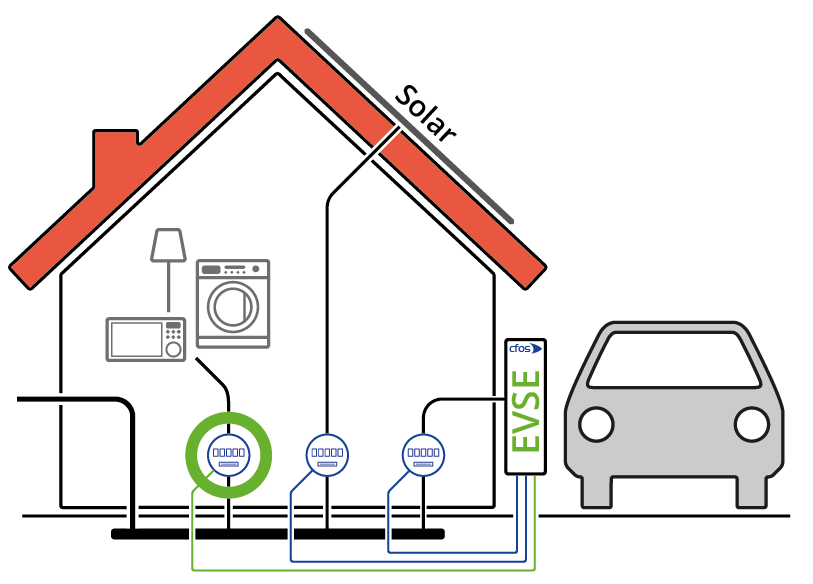
Possible uses for the meter
1. Logging of the charged kWh
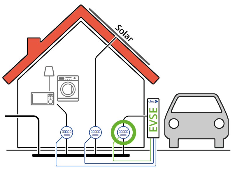
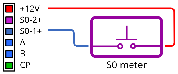
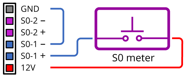
Ask your electrician to install the S0 meter in the electrical distribution in the supply lines for the cFos Power Brain Controller. You must have a twisted pair connection wired from the S0 meter to the "S0-1" connection of the cFos Power Brain Controller. For Modbus meters, you must have the A and B connections of the Modbus meter connected with twisted pair to the A and B connections of the cFos Power Brain Controller.
In the "Configuration" dialogue you need the following settings:
S0 meter
Add a meter of the type "cFos Power Brain Controller" as a meter.
Device type: cFos Power Brain
Address: localhost:4701
ID: 1
Enabled: on
Role: Display or consumption e-car
If necessary, set the number of pulses per kWh.
Modbus meter
Add a meter of the type "cFos / YTL DTS353F-2" as the meter.
Device type: cFos / YTL DTS353F-2
Address: COM1,9600,8,e,1
ID: 101
Enabled: an
Role: display or consumption E-car
From now on, your cFos Power Brain Controller counts the energy charged to the car.
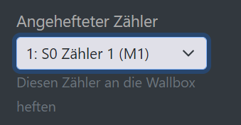
Note: In order for the EVSE to know about this meter, you must pin this S0 meter in the settings for the EVSE.
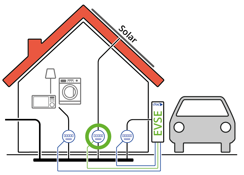
2. Dynamic Charge Current Control with Consideration of Home Consumption
Unique selling point: we know of no other EVSE that can do this.
Ask your electrician to install the meter behind your energy supplier's meter so that it only measures the electricity consumption in your house - without that of the cFos Power Brain Wallbox. You will need to have the meter wired to the cFos Power Brain Controller as above.
Activate "Load management" in the configuration of the cFos Power Brain Controller.
In the "Configuration" dialogue you need the following settings:
Enter your house connection capacity under "Max. Total power". You should definitely enter 3000 (3 kW) as the control reserve under "Power reserve (", because individual phases could be loaded differently.
Add the cFos Power Brain Wallbox as EVSE (EVSE).
Device type: cFos Power Brain
Address: localhost:4701
ID: 1
Enabled: an
Max. Power: 11kW
Priority: 0
Phase rotation: 0
Add the type S0 meter or Modbus meter as the meter, as explained above. Role: Consumption
Save all settings. From now on, the Charging Manager integrated in the cFos Power Brain Controller reduces the charging power of your car if the house consumption increases for a short time, e.g. by using an instantaneous water heater. As soon as consumption has dropped again, the full charging power is available to the car again.
If you add a second (supported) EVSE later, the Charging Manager can also distribute the available power to both EVSEs.
3. Charging only when the solar system provides sufficient power
Here you will find instructions for PV surplus charging (solar surplus charging)
If the Charging Manager cannot read the inverters of your solar system, ask your electrician to install the meter behind the inverter of your solar system so that it measures how much power the solar system is currently generating. You will need to have the meter wired to the cFos Power Brain Controller using a twisted pair connection as explained above.
Activate "Load management" in the configuration of the cFos Power Brain Controller.
You need the following settings in the "Configuration" dialog:
Enter your house connection capacity under "Max. Total power". You should definitely enter 3000 (3 kW) as the control reserve under "Power reserve (", because individual phases could be loaded differently.
Add the cFos Power Brain Wallbox as EVSE (EVSE).
Device Type: cFos Power Brain
Address: localhost:4701
ID: 1
Enabled: on
Max. Power: 11kW
Priority: 0
Phase rotation: 0
Click on "Add charging rule" to add a charging rule. Select "Solar" as the rule type and enter the desired power of the solar system as of which the car is to be charged as the "Start current limit". Enter the desired charging power for the car under "Current". You do not have to select the entire solar power if you want to operate other devices with the solar system. Select "Absolute", for example, if the charging power is to be set as an absolute wattage.
Save the cFos Power Brain Controller settings.
Add the type S0 meter or Modbus meter as meter, as explained above.
Role: Generation
Save the settings of the meter and the house connection power. From now on, the Charging Manager will allocate the share of solar power you have selected to the car for charging.
Notes
Some S0 meters have a semiconductor pulse output. If you do not register any pulses, you must swap the lines at the S0 input. Under "Configuration" you will find a display under "Hardware" of how many pulses have been registered at the S0 inputs. With Modbus meters, inputs A and B may be reversed. Here you may have to reverse the polarity.
You can also combine both variants: Connect one meter to measure domestic consumption and another meter to measure solar power.
In these examples, we operate the cFos Power Brain Controller as a Modbus TCP device. localhost:4701 is the EVSE, localhost:4702 the S0 counter input 1 and localhost:4703 the S0 counter input 2.
The EVSE has slave ID 1, the S0 counter input 1 has ID 2 and the S0 counter input 2 has ID 3.
Take care not to overload the S0 intermediate counters and make sure that the maximum capacity of the counter according to the data sheet is not exceeded.