Documentation
Overview of configuration examples for cFos Power Brain / Charging Manager
Below are some configuration examples. Click on the links below to go directly to your example:
- 1 EVSE, 1 meter solar with charge controller
- 1 wallbox, 1 meter consumption e-car, solar system Sunspec, solar surplus
- 1 EVSE, 1 meter E-car consumption
- 1 EVSE, 1 meter consumption house
- 1 Wallbox, 1 Mains supply meter
- 1 wallbox, 1 meter Mains supply (bidirectional)
- 2 EVSEs, 1 meter for domestic consumption
- 2 EVSEs, 1 meter for domestic consumption, 1 inverter
- 2 EVSEs, 1 meter domestic consumption, 1 meter unknown solar system
- 2 EVSEs, static house connection
- 2 EVSEs, static house connection, two attached meters for the EVSEs
- 2 EVSEs, static house connection, two attached meters for the EVSEs, second EVSE Modbus RTU
- 2 EVSEs, static house connection, two attached Modbus meters for the EVSEs, second EVSE Modbus RTU
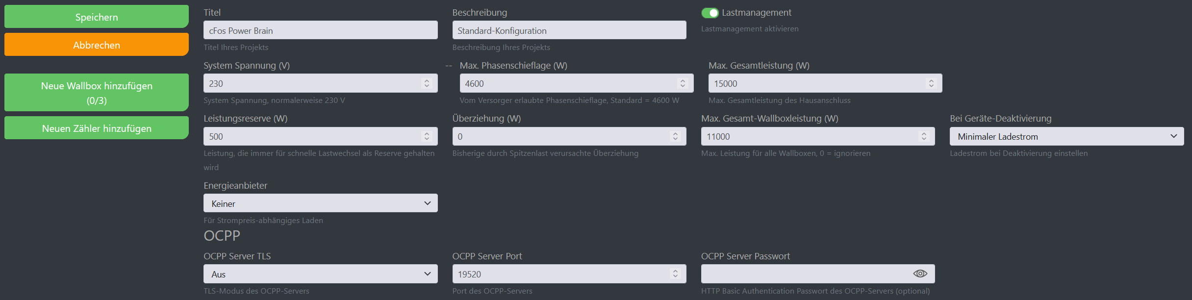
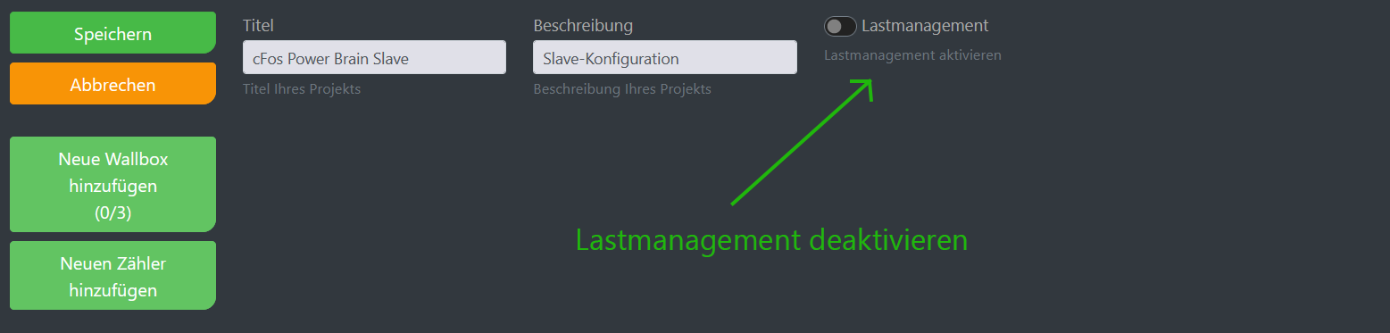
In the examples below, a cFos Power Brain Wallbox with included cFos Charging Manager is used as the central control unit. Alternatively, you can also use a Raspberry Pi. The cFos Charging Manager (already integrated in the cFos Power Brain Wallbox) can control EVSEs and meters via LAN/WLAN (Modbus TCP/IP) and (twisted) pair (modbus RTU). A Modbus proxy is also supported, allowing you to combine both. For more information on the connection options, see: Connection options.
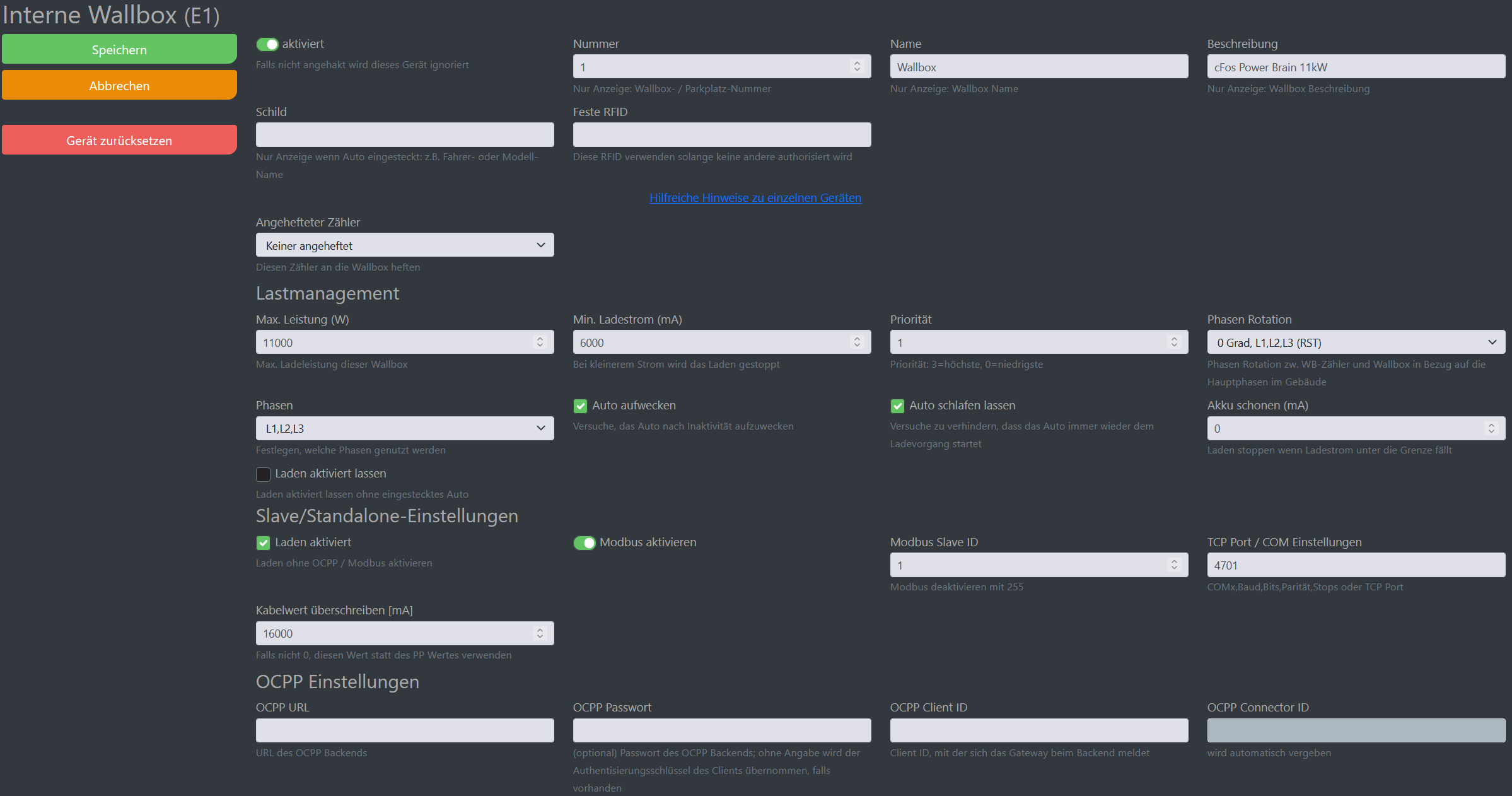
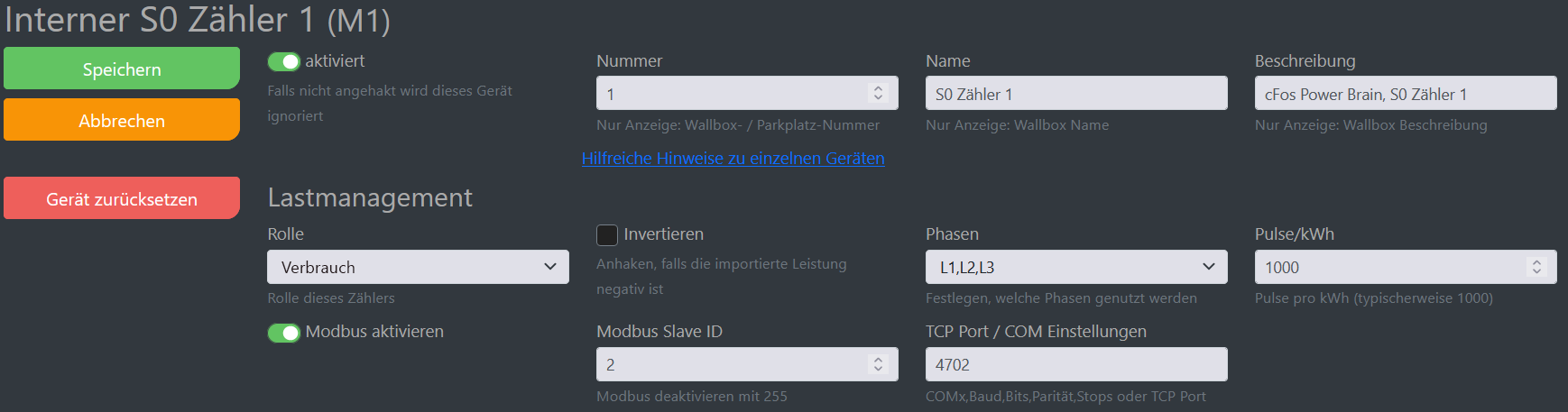
In the cFos Power Brain Wallbox, the "internal" EVSE and the internal S0 meters 1 and 2 are always set up as devices and are displayed as tiles. These cannot be deleted, but only deactivated if necessary. EVSE and S0 meter 1 are activated, S0 meter 2 is deactivated. In order to see the tile of S0 meter 2 and configure it, you must activate the checkbox "Show all" under "Start" for "Devices". The IP address, port and Modbus ID are fixed for all these internal devices. You do not need to configure anything here. By default, the cFos Charging Manager is activated, i.e. the mode is "load sharing". This means that the cFos Power Brain Wallbox works with all functions in the default setting. If you want to operate a cFos Power Brain Wallbox as a slave, you must set the mode to "watch". Otherwise, you do not need to configure anything in the slave EVSE as long as you use default values 4701, 4702 and 4703 for TCP port for EVSE and S0 meters 1 and 2, as well as Modbus ID 1, 2 and 3.
1 EVSE, 1 meter solar, solar surplus
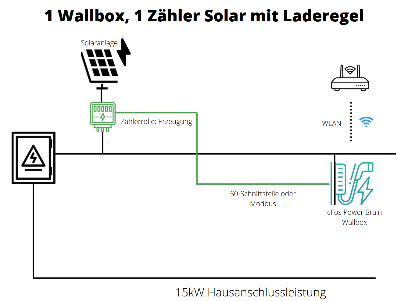


In the master EVSE (cFos Power Brain Wallbox), the internal EVSE and S0 meter 1 are already set up and activated as described above.
The role of the S0 meter is "generation", because it measures the power of the solar system.
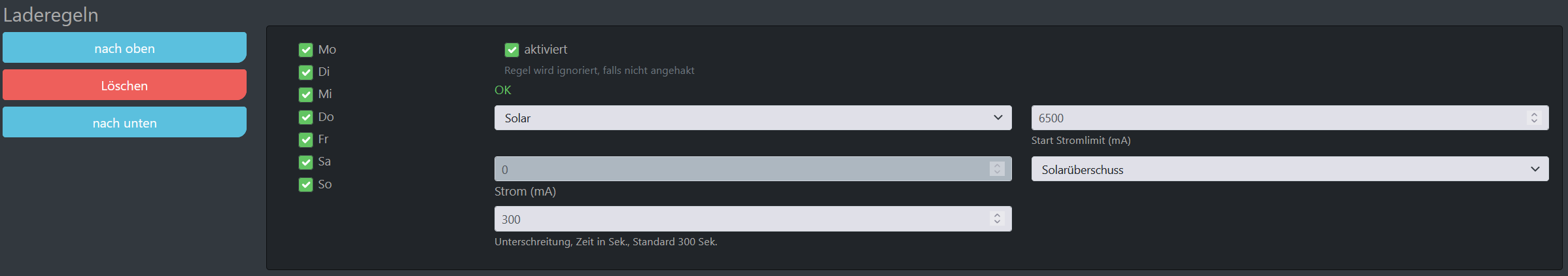
The EVSE has e.g. 15 kW house connection power plus solar power at its disposal. The charging rule ensures that charging only takes place when a minimum current of 6.5 A is reached. Excess charging
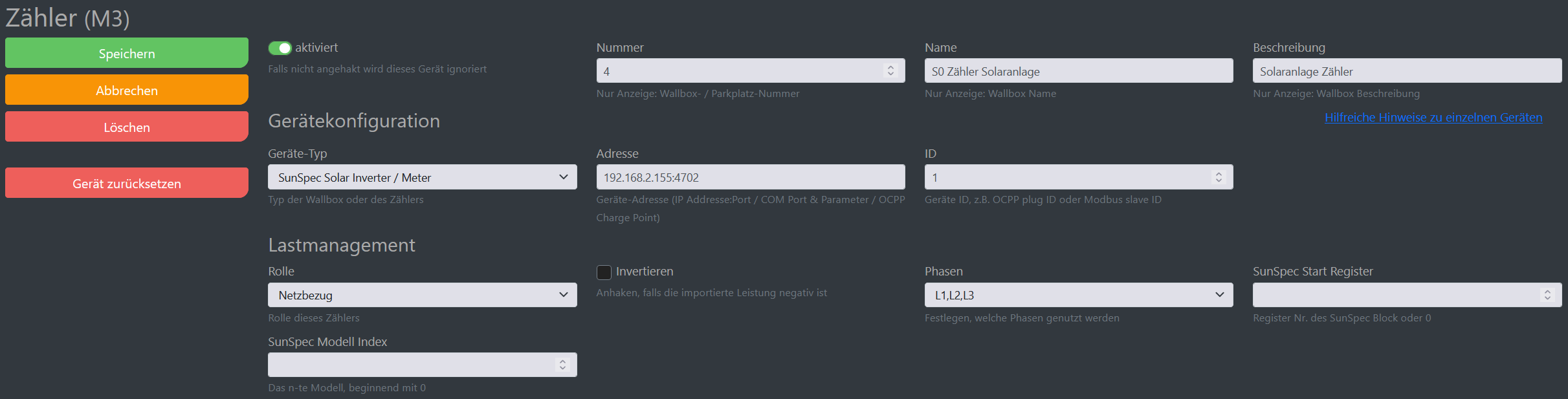
1 EVSE, 1 meter for e-car consumption, Sunspec solar system, solar surplus
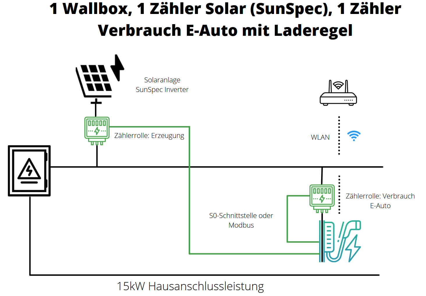
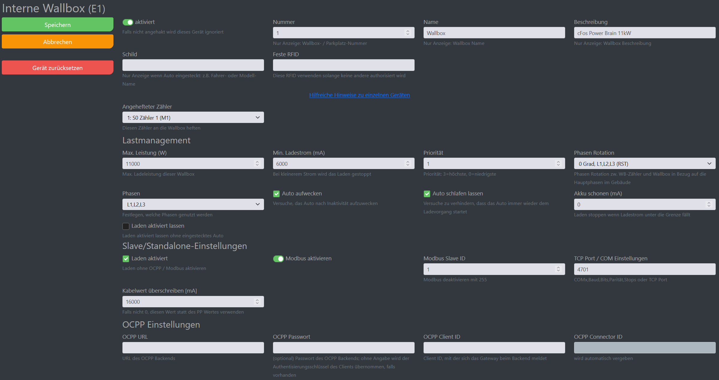
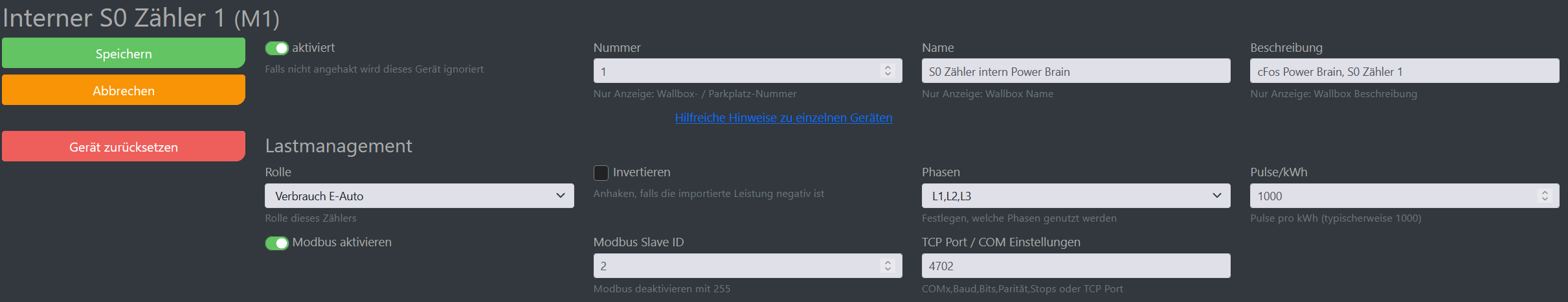
In the master EVSE (cFos Power Brain Wallbox), the internal EVSE and S0 meter 1 are already set up and activated as described above.
The S0 meter 1 of the cFos Power Brain Wallbox 11kW and is wired so that only the current drawn by the EVSE is measured. The role of the S0 meter is "consumption e-car"
The EVSE has e.g. 15 kW house connection power plus solar power at its disposal. The charging rule ensures that charging only takes place when a minimum current of 6.5 A is reached. Excess charging.
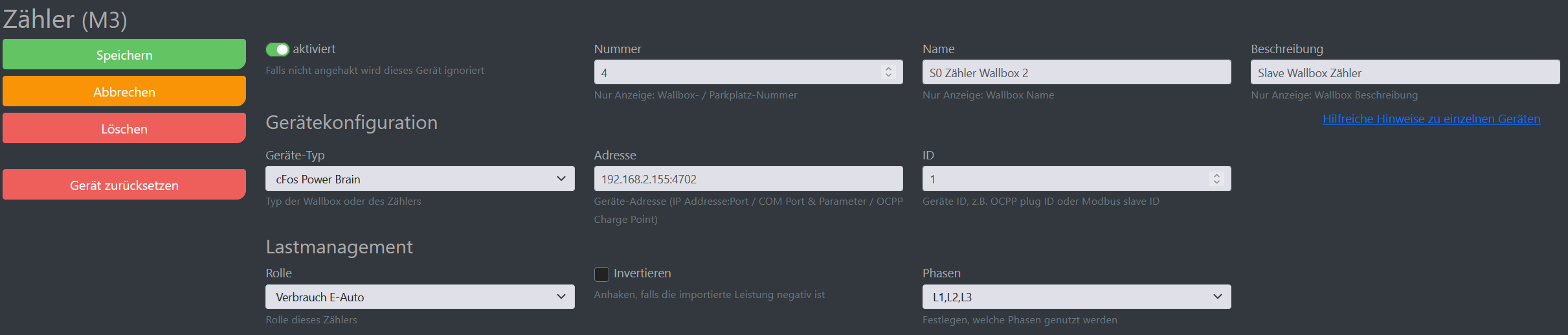
The address of the SunSpec Solar Inverter can be found in your router settings. As an example, 192.168.2.155:4702 has now been entered here
1 EVSE, 1 meter E-car consumption
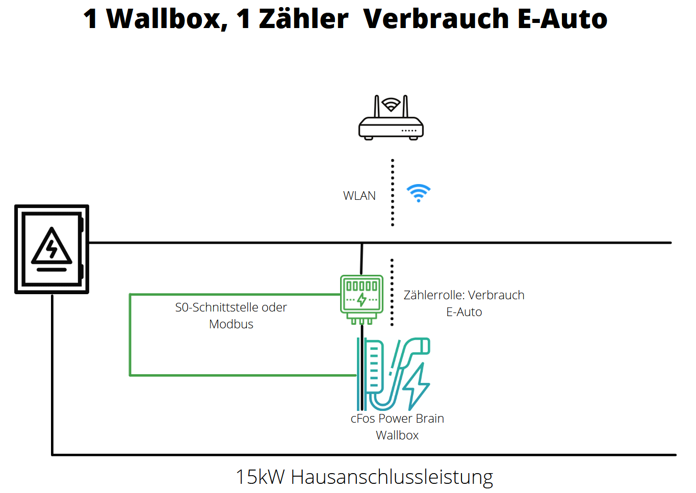
In the master EVSE (cFos Power Brain Wallbox), the internal EVSE and S0 meter 1 are already set up and activated as described above.
The S0 meter 1 of the cFos Power Brain Wallbox 11kW and is wired so that only the current drawn by the EVSE is measured. The role of the S0 meter is "E-car consumption".
The "house connection" has 15 kW. This power is statically available (as there is no house connection meter). You should set the phases of the S0 meter as the car actually uses them, i.e. mostly L1 or L1+L2+L3.
1 EVSE, 1 meter consumption house
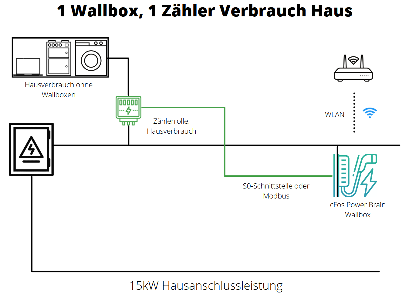
In the master EVSE (cFos Power Brain Wallbox), the internal EVSE and S0 meter 1 are already set up and activated as described above.
The S0 meter 1 of the cFos Power Brain Wallbox 11kW and is wired so that only the current drawn by the house (without the EVSE) is measured. The role of the S0 meter is "consumption".
The house connection has 15 kW. The power of the S0 meter is subtracted from this power. The rest is available for charging the e-car. If short-term load peaks occur in the house, the charging power is reduced. In order not to overbook the 15 kW, a reserve of 2 kW has been set up.
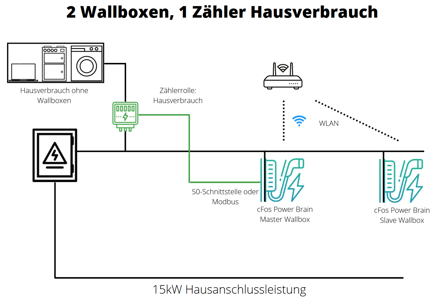
1 Wallbox, 1 Mains supply meter

In the wallbox (cFos Power Brain Wallbox), the internal wallbox and internal Modbus meter are already set up and activated as described above. The 2nd Modbus meter (role mains supply) is installed so that it measures the electricity consumed at the house connection point, i.e. wallbox consumption and house consumption. The house connection has 15 kW. The power of the 2nd Modbus meter is subtracted from this power. The rest is available for charging the e-car. If short-term load peaks occur in the house, the charging power is regulated down. In order not to overbook the 15 kW, a reserve of 2 kW has been set up.
1 wallbox, 1 meter Mains supply (bidirectional)

In the wallbox (cFos Power Brain Wallbox), the internal wallbox and internal Modbus meter are already set up and activated as described above. The 2nd Modbus meter (role grid reference) is installed so that it measures the current occurring at the house connection point, i.e. Wallbox consumption, house consumption and generation by the solar system. The house connection has 15 kW. From this power, the power of the 2nd Modbus meter is subtracted (if the meter shows positive values) or added (if the meter shows negative values, i.e. power is fed in). Taking into account the charging current of the wallbox, the Charging Manager can calculate solar surplus, but also measure the load on the house connection. If short-term load peaks occur in the house, the charging power is reduced. In order not to overbook the 15 kW, a reserve of 2 kW has been set up. In this configuration, you can set up rules for PV surplus charging.
2 EVSEs, 1 meter for domestic consumption
Setup Master Slave Operation
Both EVSEs share the house connection power of 15kW minus 500 W control reserve. The EVSE meter has the role of "consumption", i.e. it measures what the house currently needs (without EVSEes). The charging power minus the household consumption is distributed to both EVSEs. With 15kW and 500 W reserve, 14.5kW are available for charging. If the house still needs e.g. 3kW and both are charging at the same time, each EVSE receives 5.75kW charging power.
The correct Modbus ports and slave IDs must be set:
- Default for the EVSE: Port 4701, Slave ID 1
- Default for S0 meter 1: Port 4702, Slave ID 2
- Default for S0 meter 2: Port 4703, Slave ID 3
For other devices: Instructions for some EVSEes, meters and inverters
1. Master
In the master EVSE (cFos Power Brain Wallbox), the internal EVSE and S0 meter 1 are already set up and activated as described above.
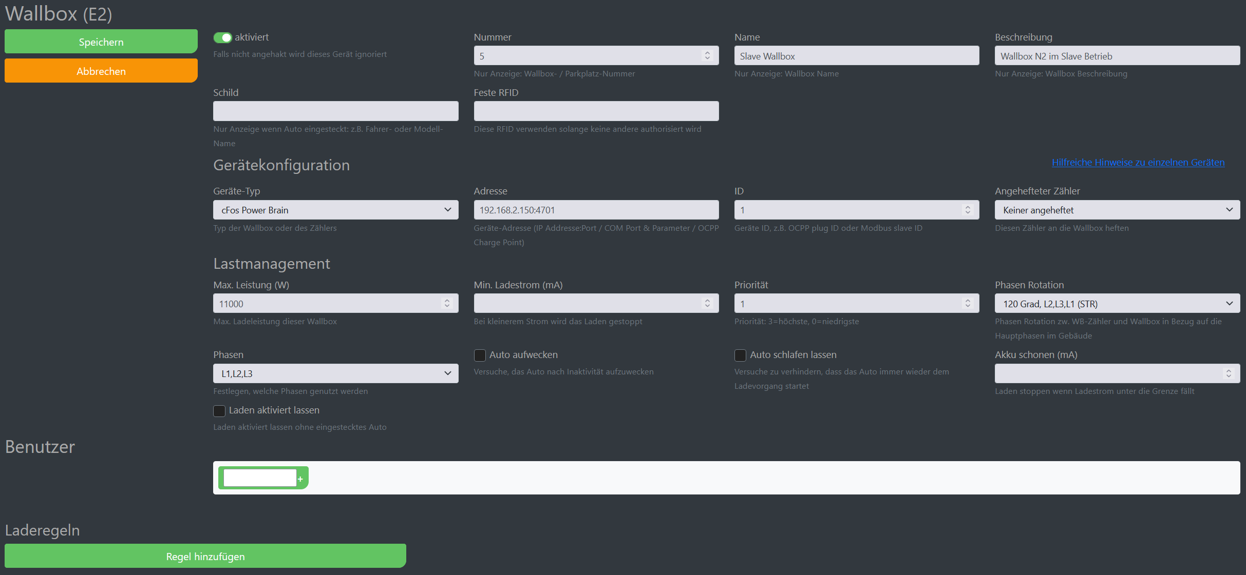
2. Slave
The 2nd EVSE (slave) is connected to the WLAN (house network). It is operated as a Modbus (TCP/IP) slave. Therefore, the address is e.g. 192.168.2.150:4701 and slave ID 1.
The slave is connected with phase rotation 120 degrees, i.e. the electrician has rotated the phases with respect to the master (L1 -> L2, L2 -> L3, L3 -> L1). This prevents one-sided phase loading when both cars are charging on L1. The cFos Charging Manager can monitor this if it can measure individual phases (not measured here, but a phase rotation of 120 degrees has already been entered for demo purposes). If both cars only charge in single phase, both can receive full power on their phase.
S0 meter :
The S0 meter is connected to the S0-1 input of the master and therefore has default values as described above. It could also hang in slave S0-1 and would then have the address 192.168.2.150:4702, slave ID 2, for example.
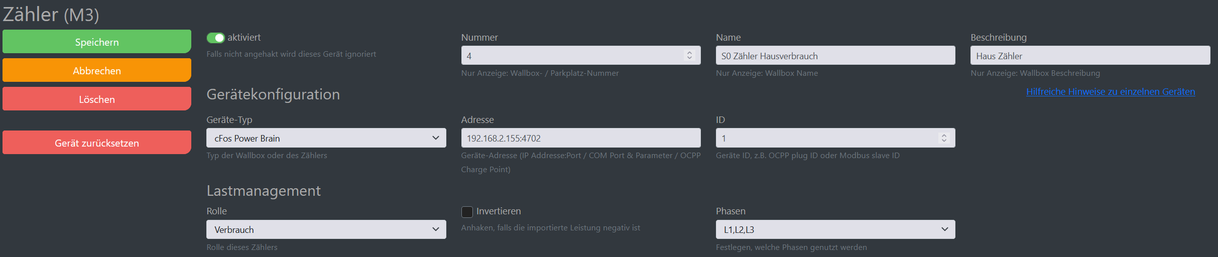
2 EVSEs, 1 meter for domestic consumption, 1 inverter
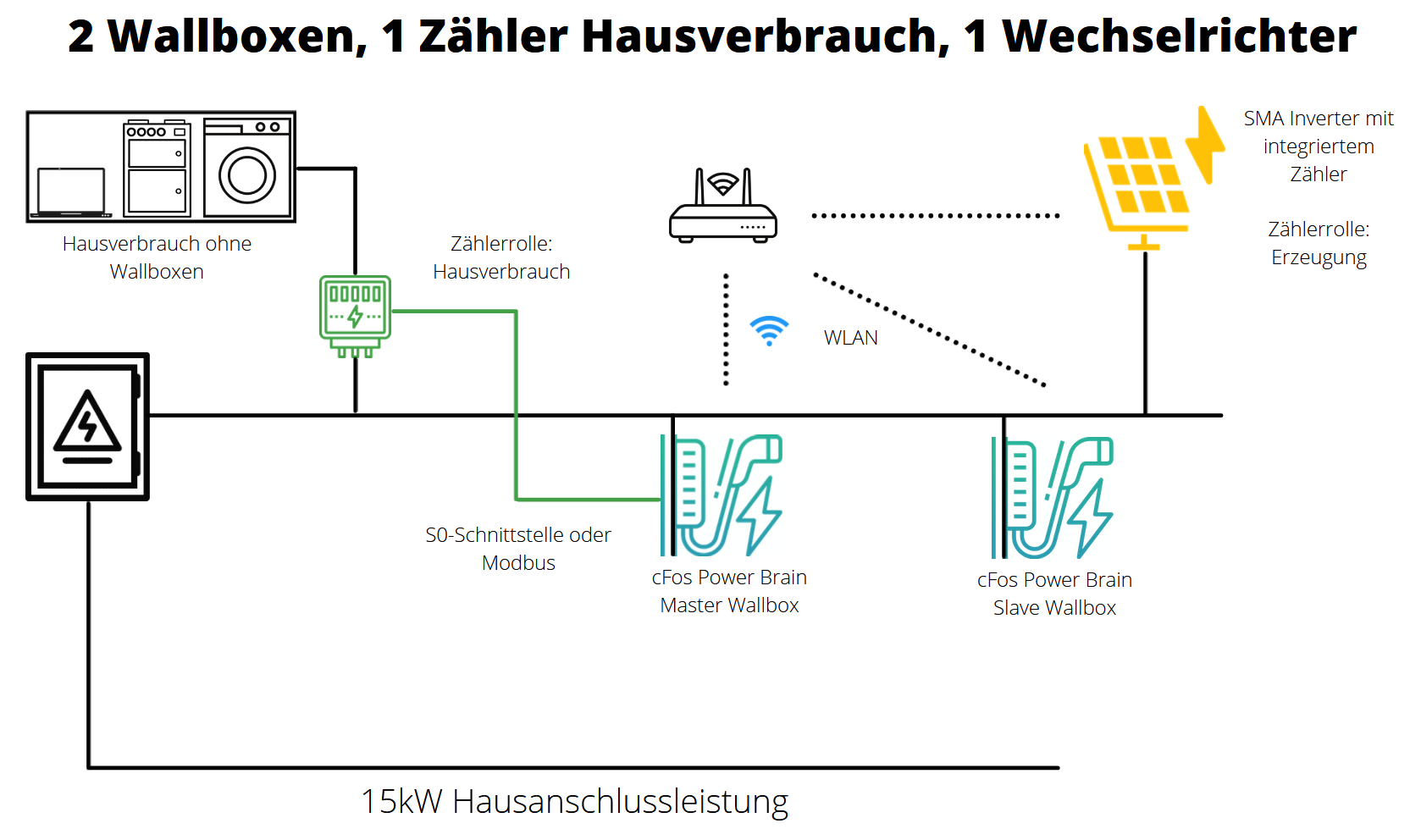

Setup Master Slave Operation
Both EVSEs share the house connection power of 15kW minus 500 W control reserve. The EVSE meter has the role of "consumption", i.e. it measures what the house currently needs (without EVSEes). The available charging power is the house connection power of 15 kW minus 500 W control reserve minus house consumption, measured with the S0 meter, plus solar power as measured by the SMA inverter. So if the house needs 2.5 kW and the solar system generates 4 kW, the EVSEs together have 15 - 0.5 - 2.5 + 4 = 16 kW available. These are split in half if both are charging at the same time.
The correct Modbus ports and slave IDs must be set:
- Default for the EVSE: Port 4701, Slave ID 1
- Default for S0 meter 1: Port 4702, Slave ID 2
- Default for S0 meter 2: Port 4703, Slave ID 3
For other devices: Instructions for some EVSEes, meters and inverters
1. Master
In the master EVSE (cFos Power Brain Wallbox), the internal EVSE and S0 meter 1 are already set up and activated as described above.
2. Slave
The 2nd EVSE (slave) is connected to the WLAN (house network). It is operated as a Modbus (TCP/IP) slave. Therefore, the address is e.g. 192.168.2.150:4701 and slave ID 1.
The slave is connected with phase rotation 120 degrees, i.e. the electrician has rotated the phases with respect to the master (L1 -> L2, L2 -> L3, L3 -> L1). This prevents one-sided phase loading when both cars are charging on L1. The cFos Charging Manager can monitor this if it can measure individual phases (not measured here, but a phase rotation of 120 degrees has already been entered for demo purposes). If both cars only charge in single phase, both can receive full power on their phase.
Meter :
The first S0 meter is connected to the S0-1 input of the master and therefore has default values as described above. It could also hang in slave S0-1 and would then have the address 192.168.2.222:502, slave ID 3, for example.
The second "meter" is therefore an SMA inverter that hangs on the WLAN (house network). It has the role "generation".
2 EVSEs, 1 meter domestic consumption, 1 meter unknown solar system
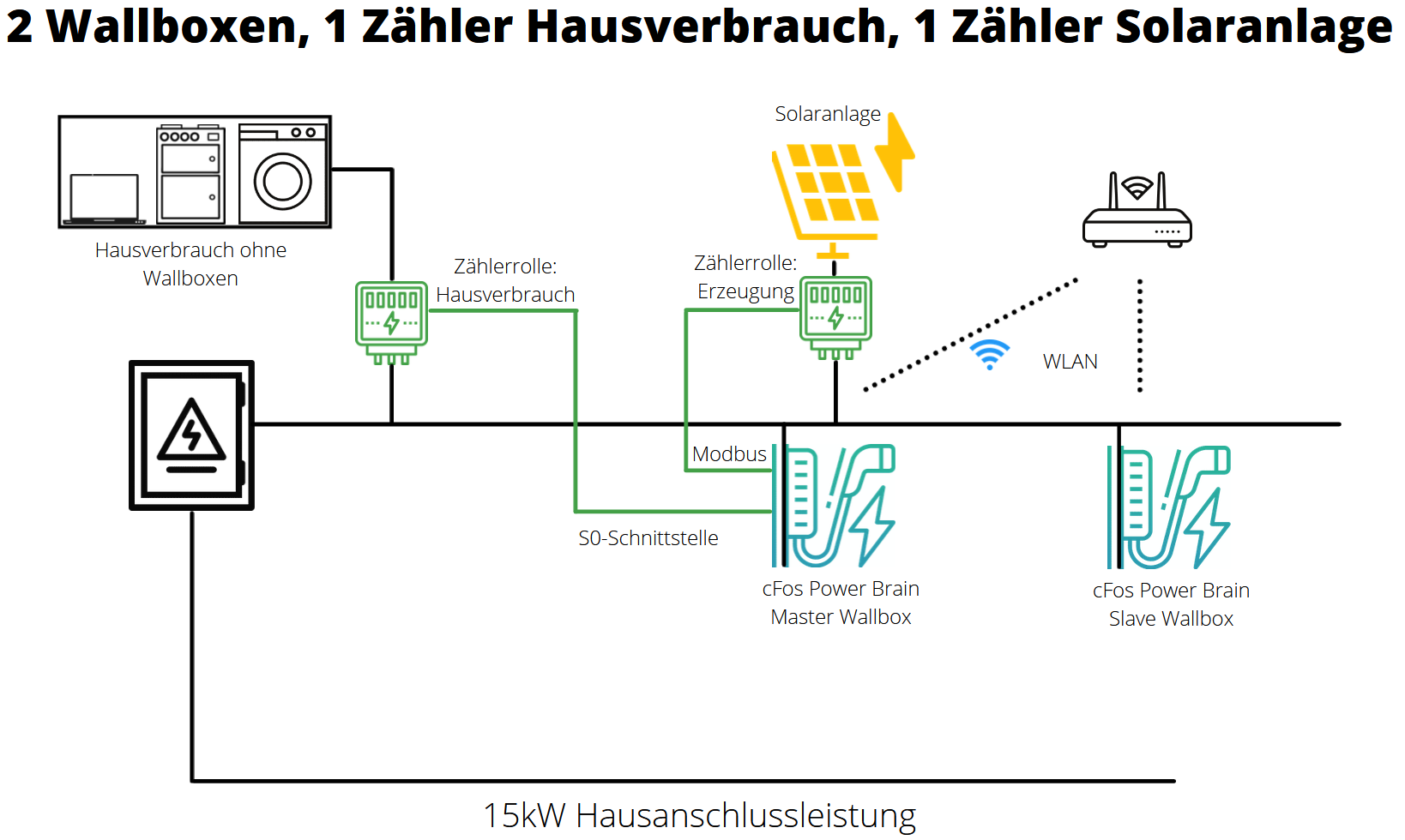
Setup Master Slave Operation
Both EVSEs share the house connection power of 15 kW minus 500 W control reserve. The current house consumption is subtracted from this power and the current solar power is added. So if the house needs 2.5 kW and the solar system generates 4 kW, the EVSEs together have 15 - 0.5 - 2.5 + 4 = 16 kW available. These are split in half if both are charging at the same time.
The correct Modbus ports and slave IDs must be set:
- Default for the EVSE: Port 4701, Slave ID 1
- Default for S0 meter 1: Port 4702, Slave ID 2
- Default for S0 meter 2: Port 4703, Slave ID 3
For other devices: Instructions for some EVSEes, meters and inverters
1. Master
In the master EVSE (cFos Power Brain Wallbox), the internal EVSE and S0 meter 1 are already set up and activated as described above.
2. Slave
The 2nd EVSE (slave) is connected to the WLAN (house network). It is operated as a Modbus (TCP/IP) slave. Therefore, the address is e.g. 192.168.2.150:4701 and slave ID 1.
The slave is connected with phase rotation 120 degrees, i.e. the electrician has rotated the phases with respect to the master (L1 -> L2, L2 -> L3, L3 -> L1). This prevents one-sided phase loading when both cars are charging on L1. The cFos Charging Manager can monitor this if it can measure individual phases (not measured here, but a phase rotation of 120 degrees has already been entered for demo purposes). If both cars only charge in single phase, both can receive full power on their phase.
Meter :
The first S0 meter is connected to the S0-1 input of the master and therefore has default values as described above. It counts the house consumption and therefore has the role "consumption".
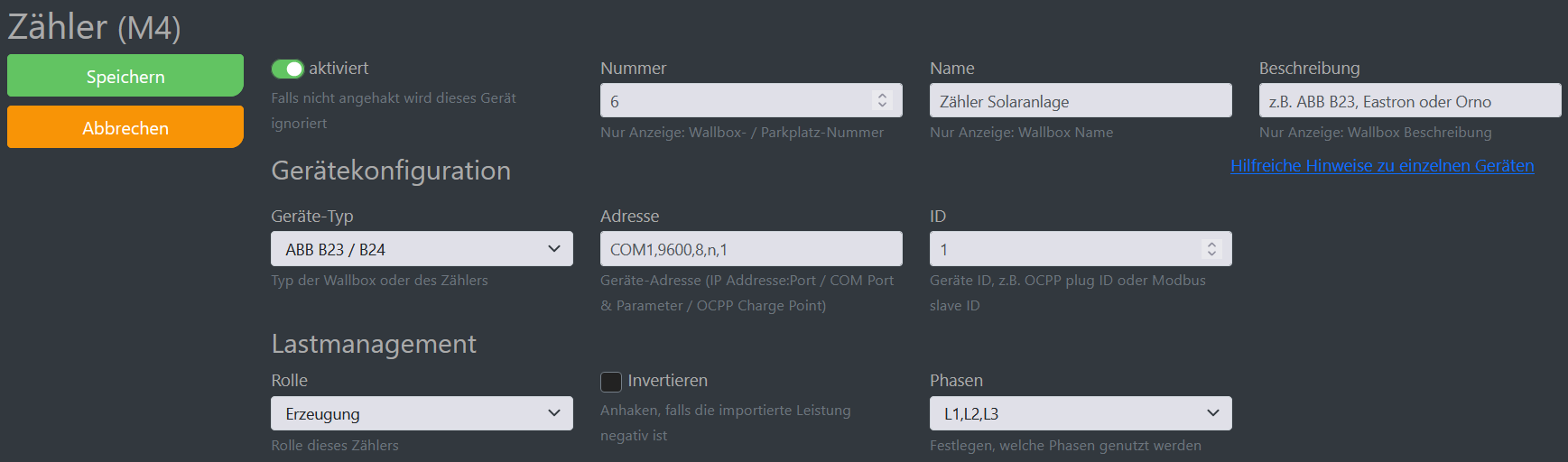
The second meter could be a Modbus meter, e.g. ABB B23, Eastron or Orno and hangs on a Modbus 2-wire connection on the Modbus terminal of the cFos Power Brain Wallbox (master) and as COM parameters the meter is set to 9600 baud, 8 data bits, no parity and 1 stop bit. Its slave ID is 1. Its role is "generation", because it measures the power of the solar system.
2 EVSEs, static house connection
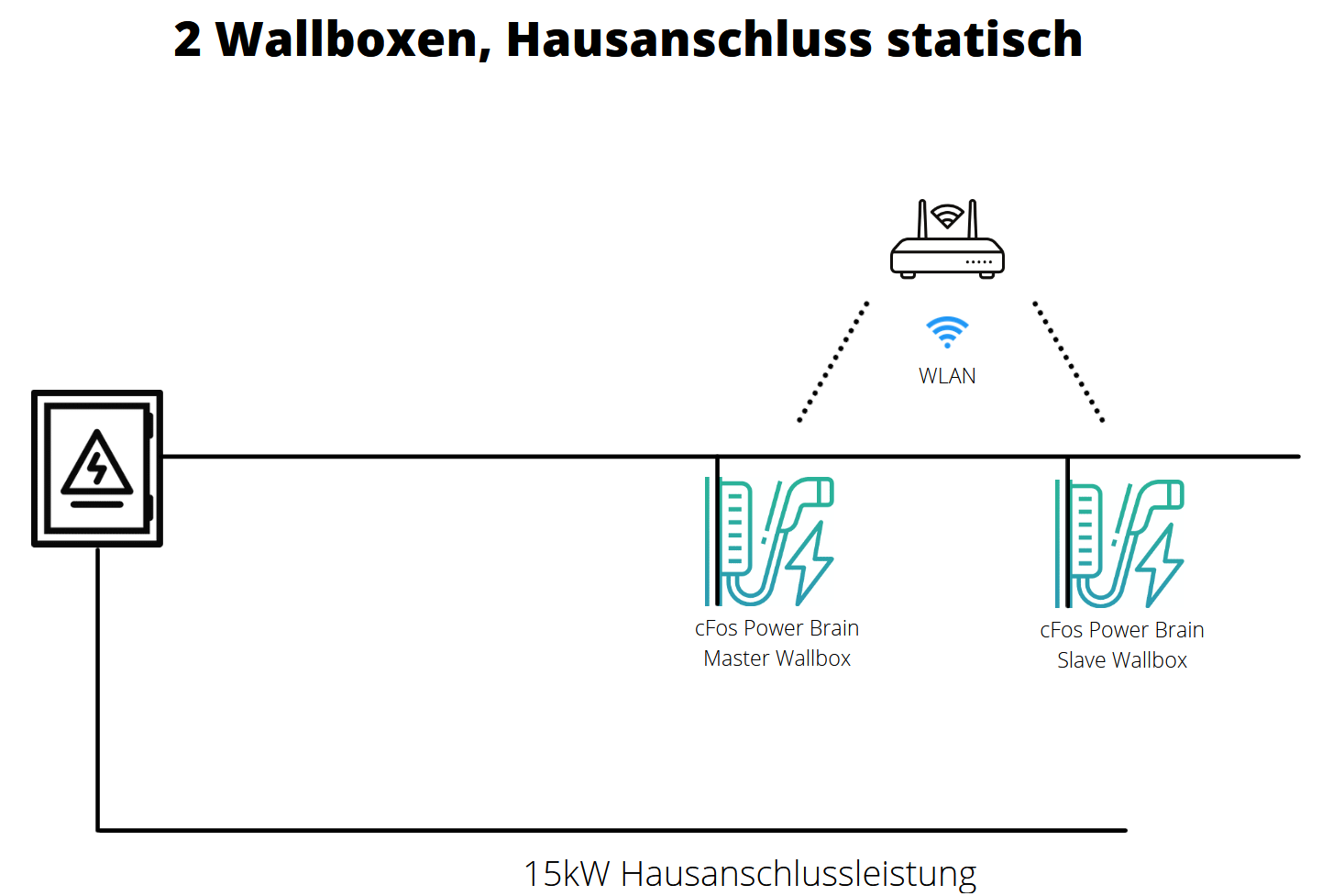
Setup Master Slave Operation
Both EVSEs share the statically allocated 15 kW. This means that if only one is charging, it receives 11 kW. If both are charging at the same time, both receive 7.5 kW (minus 500 W set control reserve).
The correct Modbus ports and slave IDs must be set:
- Default for the EVSE: Port 4701, Slave ID 1
- Default for S0 meter 1: Port 4702, Slave ID 2
- Default for S0 meter 2: Port 4703, Slave ID 3
1. Master
The internal EVSE and S0 meter 1 are already set up and activated in the master EVSE (cFos Power Brain Wallbox) as described above.
2. Slave
The second EVSE (slave) is connected to the WLAN (house network). It is operated as a Modbus slave. The IP address in the EVSE is entered here as the address for this EVSE (e.g. 192.168.2.150). Port for the EVSE is 4701, slave ID 1.
The slave is connected with phase rotation 120 degrees, i.e. the electrician has rotated the phases with respect to the master (L1 -> L2, L2 -> L3, L3 -> L1). This prevents one-sided phase loading when both cars are charging single-phase or two-phase. If both cars only charge in single phase, both can receive full power on their phase. The cFos Charging Manager can monitor this if it can measure individual phases (not measured here, but a phase rotation of 120 degrees has already been entered for demo purposes). The charging power is divided among the charging cars. If no meters are connected, the cFos Charging Manager assumes that the car always takes the power offered to it. Without meters, you can permanently set which phases are used by the car.
2 EVSEs, static house connection, 2 meters attached to the EVSEs
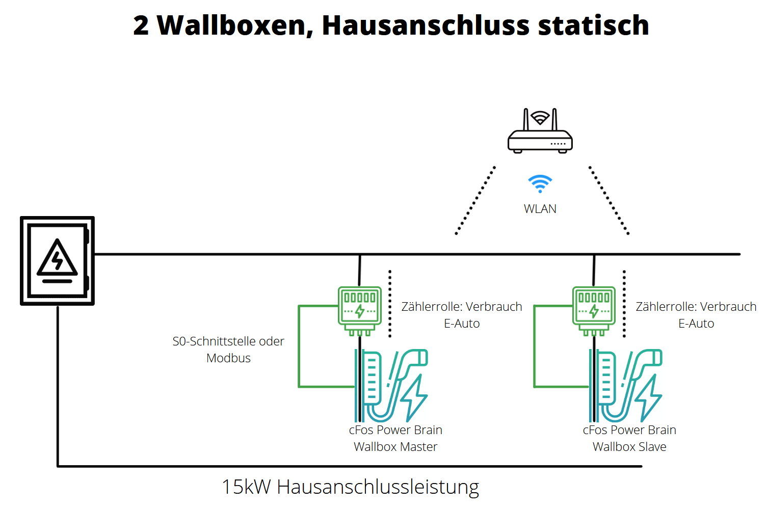

Setup Master Slave Operation
Both EVSEs share the statically allocated 15 kW. This means that if only one is charging, it receives 11 kW. If both are charging at the same time, both receive 7.5 kW (minus 500 W set control reserve). The attached meters allow the Charging Manager to allocate more than 7.5 kW to one EVSE if the other EVSE currently requires less.
The correct Modbus ports and slave IDs must be set:
- Default for the EVSE: Port 4701, Slave ID 1
- Default for S0 meter 1: Port 4702, Slave ID 2
- Default for S0 meter 2: Port 4703, Slave ID 3
For other devices: Instructions for some EVSEes, meters and inverters
1. Master
In the Master EVSE (cFos Power Brain Wallbox), the internal EVSE and S0 meter 1 are already set up and activated as described above.
The first S0 meter is pinned here. For the Charging Manager, it looks as if the meter has been installed. A tile for the meter in the overview window disappears.
2. Slave
The second EVSE (slave) is connected to the WLAN (house network). It is operated as a Modbus slave. The IP address in the EVSE is entered here as the address for the EVSEes (e.g. 192.168.2.150). Port for the EVSE is 4701, slave ID 1.
The slave is connected with phase rotation 120 degrees, i.e. the electrician has rotated the phases with respect to the master (L1 -> L2, L2 -> L3, L3 -> L1). This prevents one-sided phase loading when both cars are charging single-phase or two-phase. If both cars only charge in single phase, both can receive full power on their phase. The cFos Charging Manager can monitor this if it can measure individual phases (not measured here, but a phase rotation of 120 degrees has already been entered for demo purposes). The charging power is divided among the charging cars. If no meters are connected, the cFos Charging Manager assumes that the car always takes the power offered to it.
The second S0 meter is pinned here. For the Charging Manager, it looks like the meter is built in. A tile for the meter in the overview window disappears.
Meter :
The first S0 meter is attached to the S0-1 input of the master and therefore has default values as described above. It counts the consumption of EVSE 1 or the master EVSE.
The second S0 meter is connected to the S0-1 input of the slave and therefore has the address e.g. 192.168.2.150:4702, Slave ID 2. Its role is "consumption-auto", because it measures the consumption of the slave EVSE.
The second S0 meter could also be attached to the internal EVSE of the slave. Then it would look to the cFos Charging Manager as if the slave EVSE had a built-in meter and therefore no meter would need to be configured for this EVSE in the cFos Charging Manager of the master.
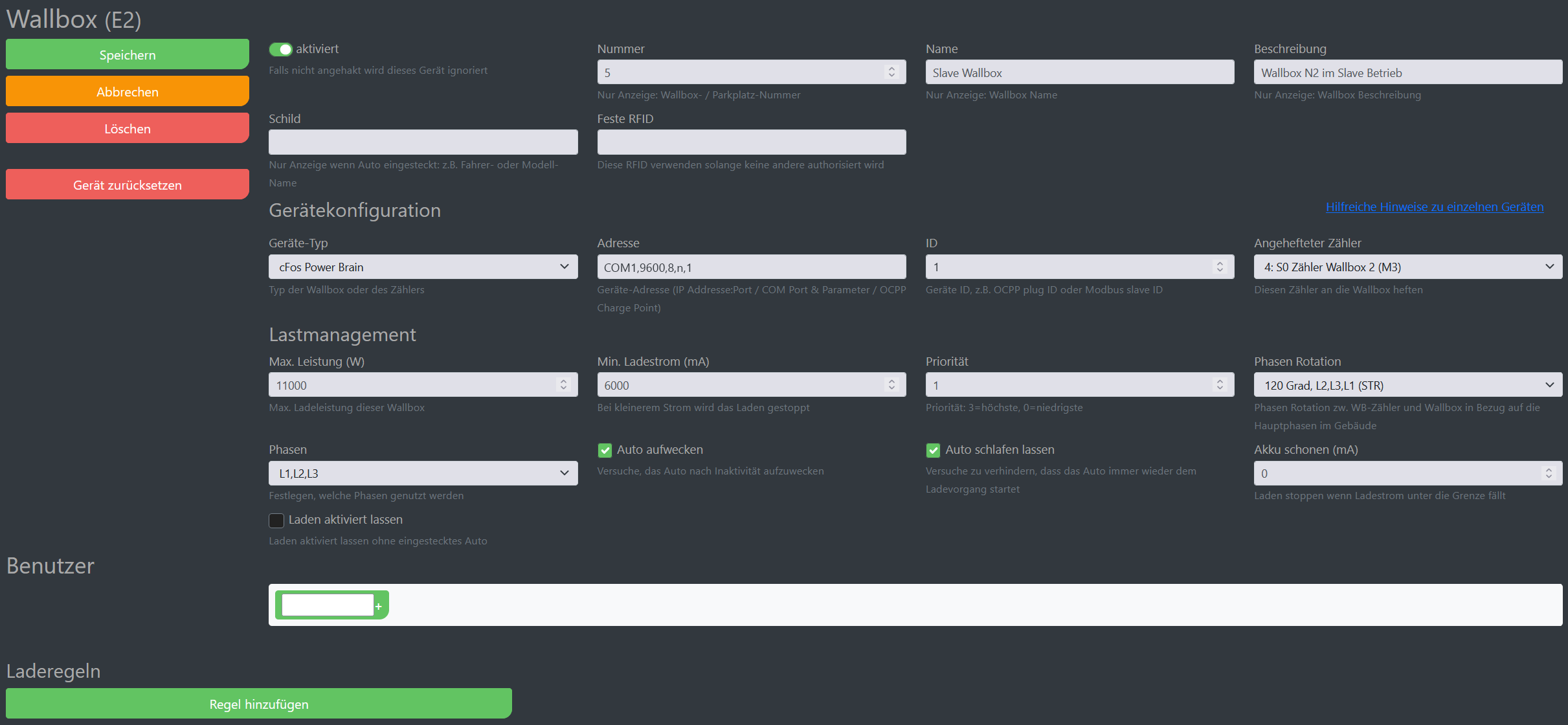
2 EVSEs, static house connection, 2 meters attached to the EVSEs, second EVSE Modbus RTU
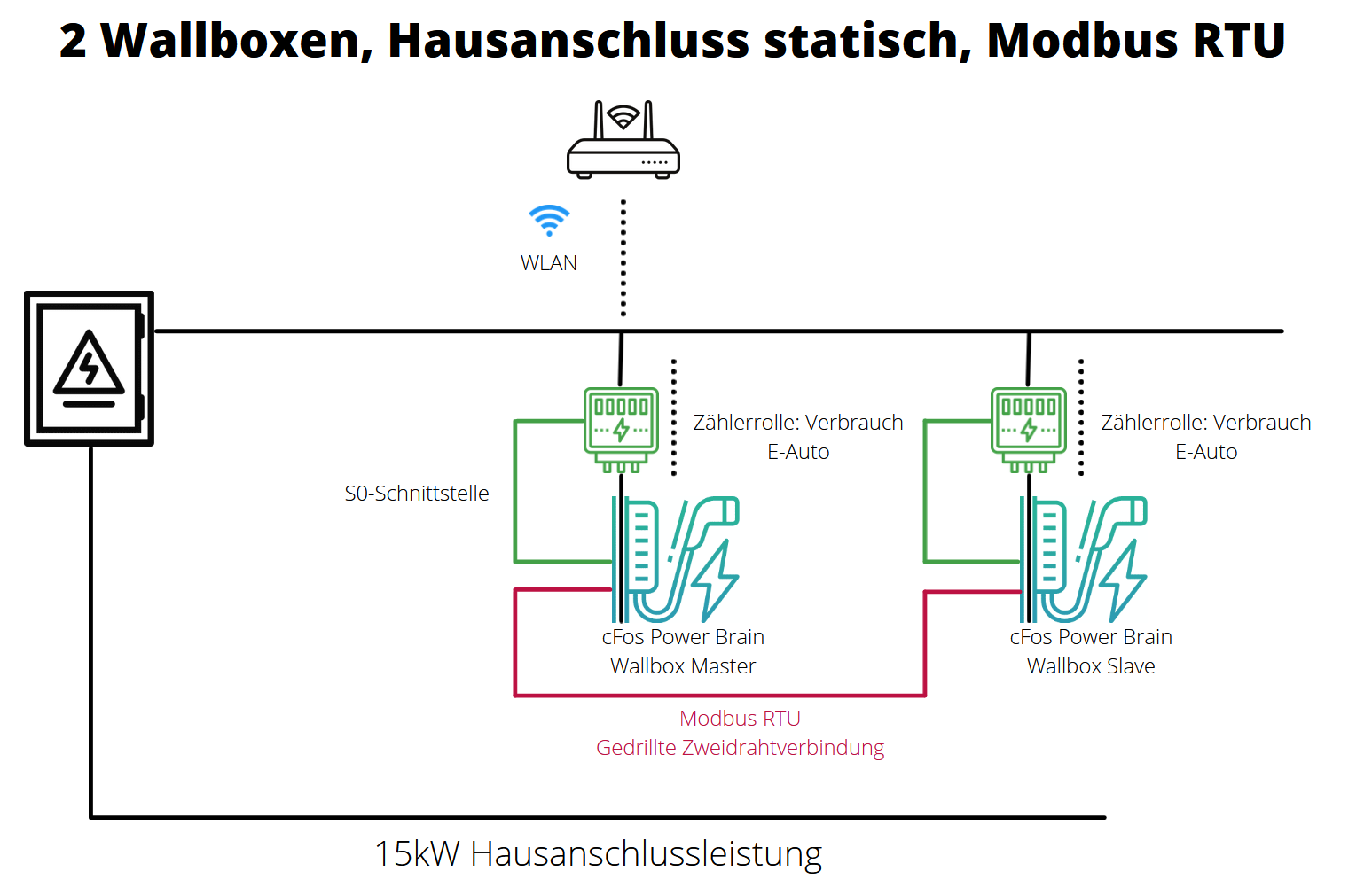
View from the Master EVSE:
View from the slave EVSE:
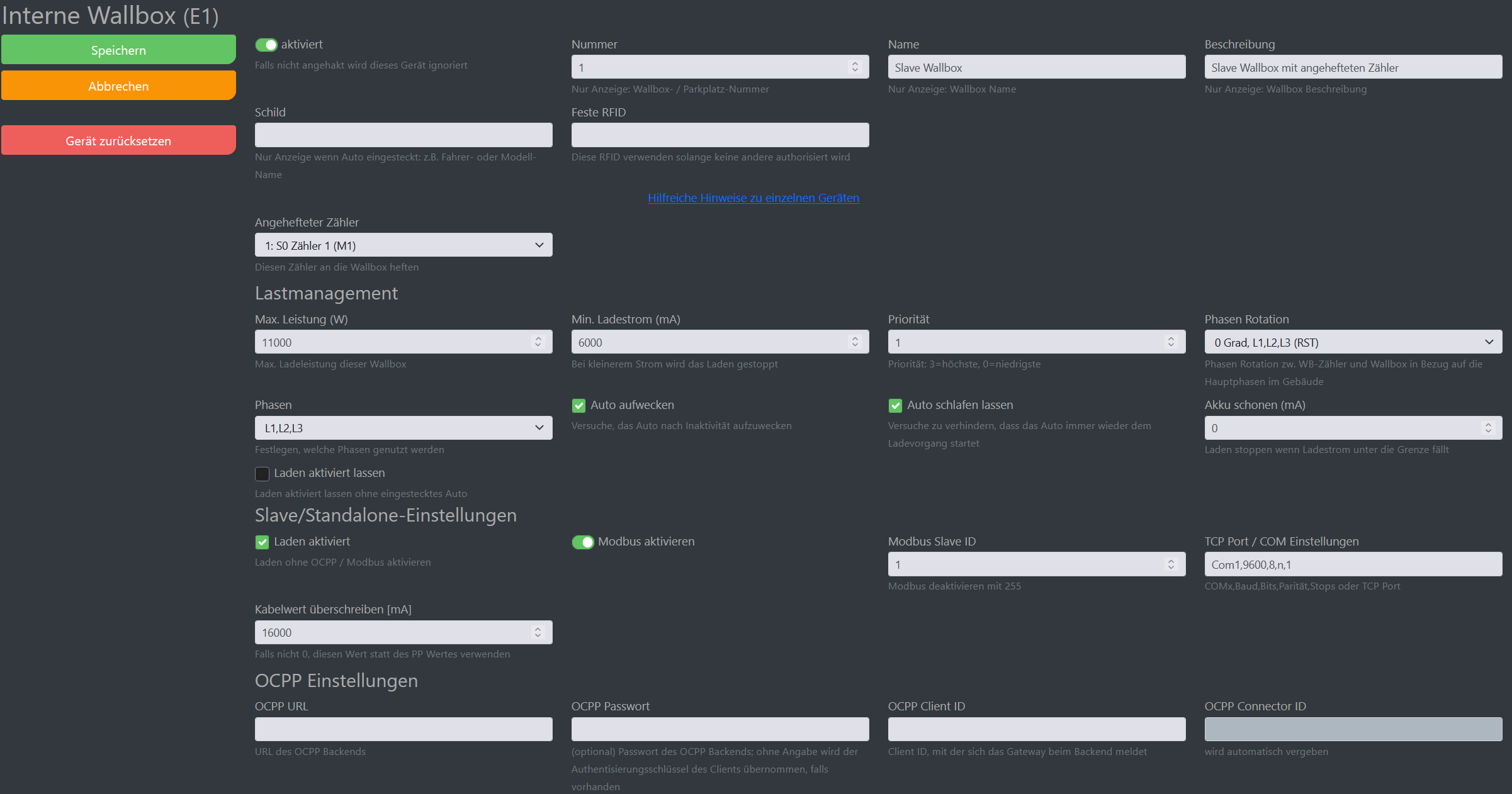
Setup Master Slave Operation
Both EVSEs share the statically allocated 15 kW. This means that if only one is charging, it receives 11 kW. If both are charging at the same time, both receive 7.5 kW (minus 500 W set control reserve). The attached meters allow the Charging Manager to assign more than 7.5 kW to one EVSE if the other EVSE currently requires less.
The correct Modbus ports and slave IDs must be set:
- Default for the EVSE: Port 4701, Slave ID 1
- Default for S0 meter 1: Port 4702, Slave ID 2
- Default for S0 meter 2: Port 4703, Slave ID 3
For other devices: Instructions for some EVSEes, meters and inverters
1. Master
In the Master EVSE (cFos Power Brain Wallbox), the internal EVSE and S0 meter 1 are already set up and activated as described above.
The first S0 meter is pinned here. For the Charging Manager, it looks like the meter is built in. A tile for the meter in the overview window disappears.
2. Slave
The second EVSE (slave) is connected to the master EVSE via Modbus RTU with a twisted pair connection. It is operated as a Modbus slave. For example, the COM port parameters were entered as the address: COM1,9600,8,n,1 and ID is 1.
The slave is connected with phase rotation 120 degrees, i.e. the electrician has rotated the phases with respect to the master (L1 -> L2, L2 -> L3, L3 -> L1). This prevents one-sided phase loading when both cars are charging single-phase or two-phase. If both cars only charge in single phase, both can receive full power on their phase. The cFos Charging Manager can monitor this if it can measure individual phases (not measured here, but a phase rotation of 120 degrees has already been entered for demo purposes). The charging power is divided among the charging cars. If no meters are connected, the cFos Charging Manager assumes that the car always takes the power offered to it.
The same COM parameters must be entered in the slave.
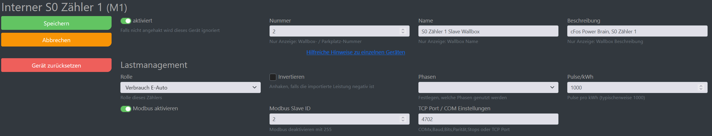
Meter :
The first S0 meter is connected to the S0-1 input of the master and therefore has default values as described above. It counts the consumption of EVSE 1 or the master EVSE.
The second S0 meter is connected to the S0-1 input of the slave and is attached to the slave and its role in the slave is set to "E-car consumption". For the Charging Manager, the slave EVSE looks like one with a built-in meter. You do not need to set up a meter for this EVSE in the cFos Charging Manager of the master.
2 EVSEs, static house connection, 2 attached Modbus meters on the EVSEs, second EVSE Modbus RTU
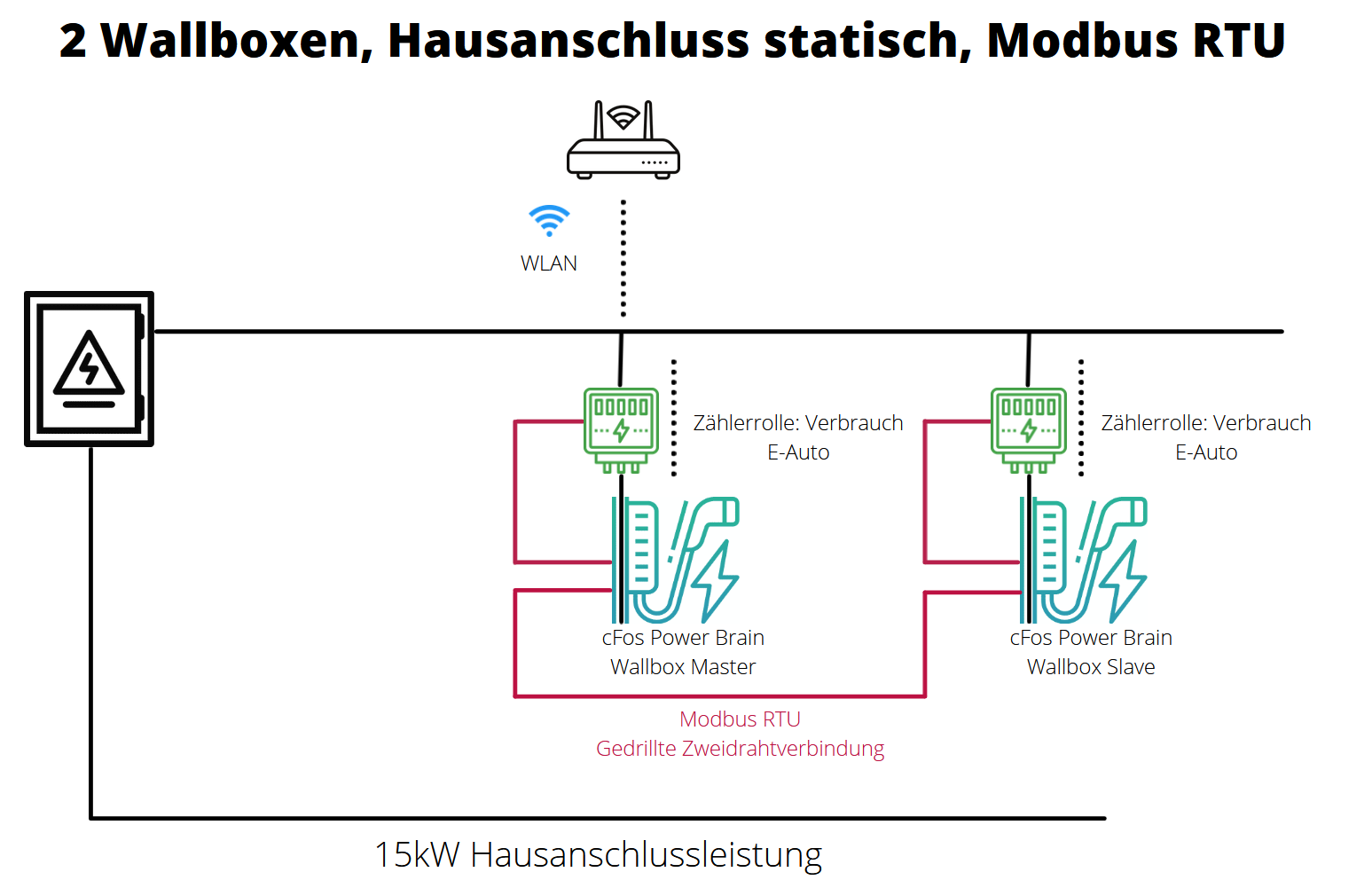
View from the Master EVSE:
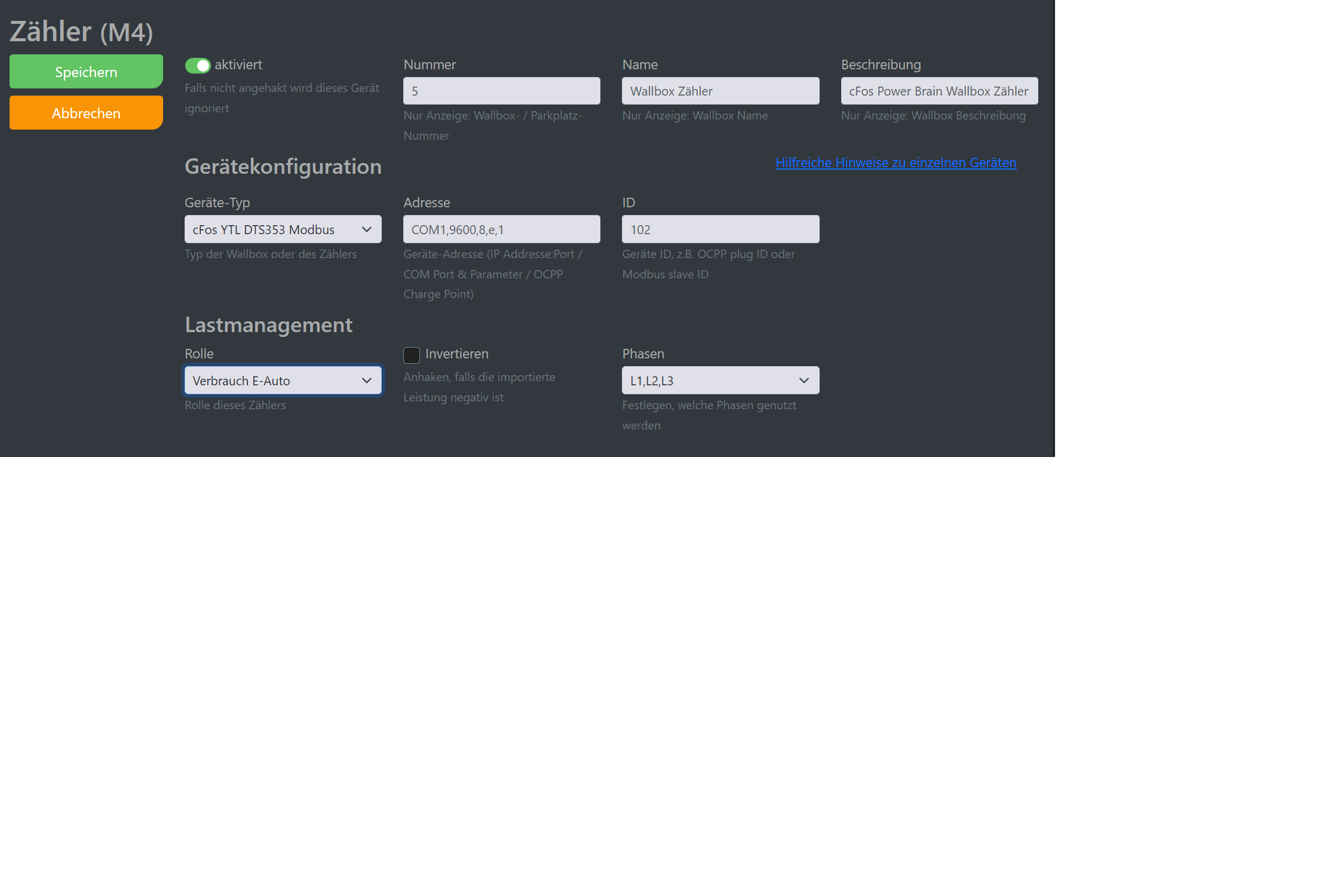
View from the slave EVSE:
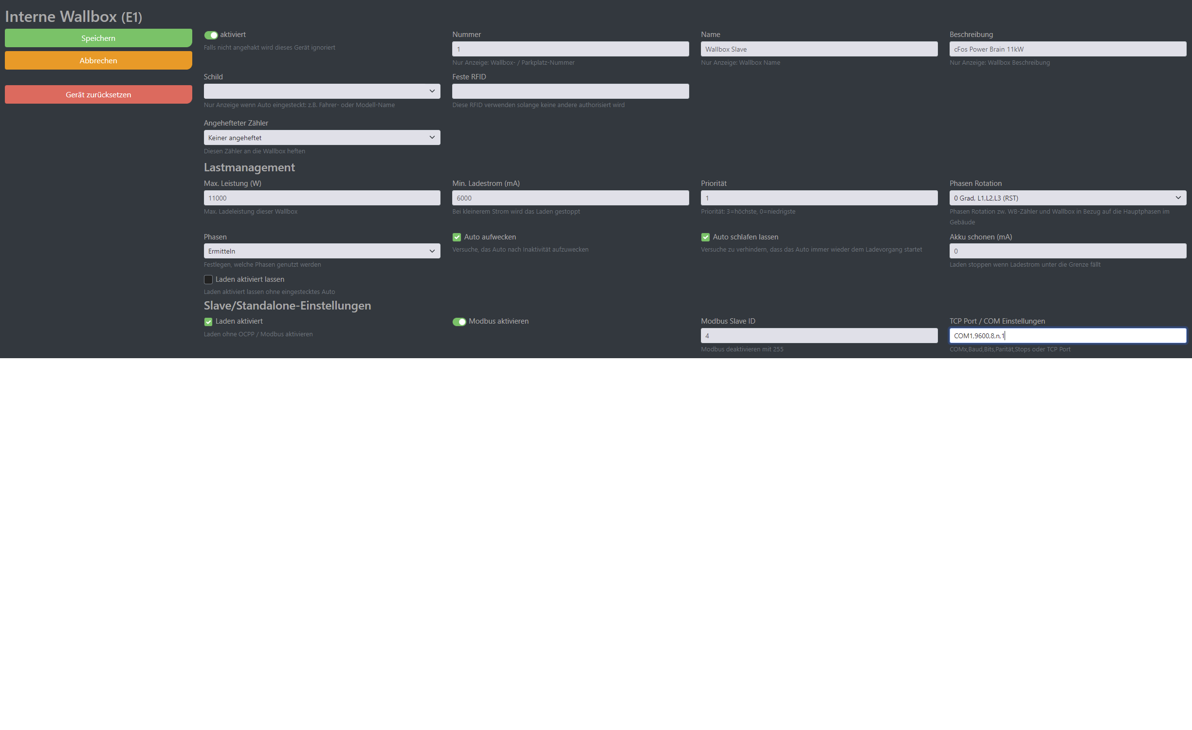
Setup Master Slave Operation
Both EVSEs share the statically allocated 15 kW. This means that if only one is charging, it receives 11 kW. If both are charging at the same time, both receive 7.5 kW (minus 500 W set control reserve). The attached meters allow the Charging Manager to assign more than 7.5 kW to one EVSE if the other EVSE currently requires less.
Both EVSEs and both meters are connected via a Modbus (RTU, two-wire connection). The slave and both meters are connected to the master. The correct Modbus ports and slave IDs must be set:
- Default for the master EVSE: Slave ID 1
- Default Modbus meter 1: Slave ID 101
- Default for the EVSE slave EVSE: Slave ID 4 (must not be 1)
- Modbus meter 2: Slave ID 102 (must not be 101)
For other devices: Instructions for some EVSEs , meters and inverters
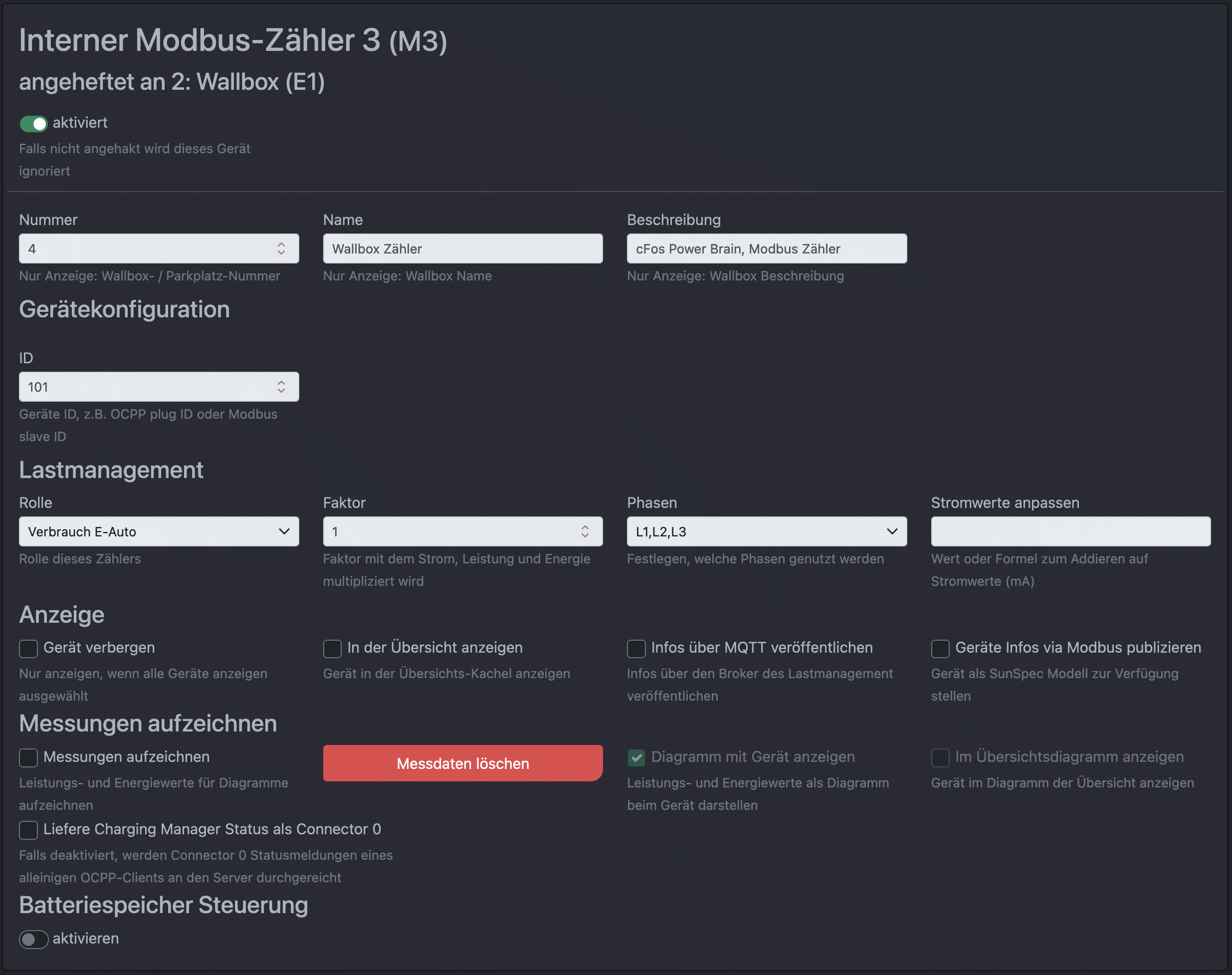
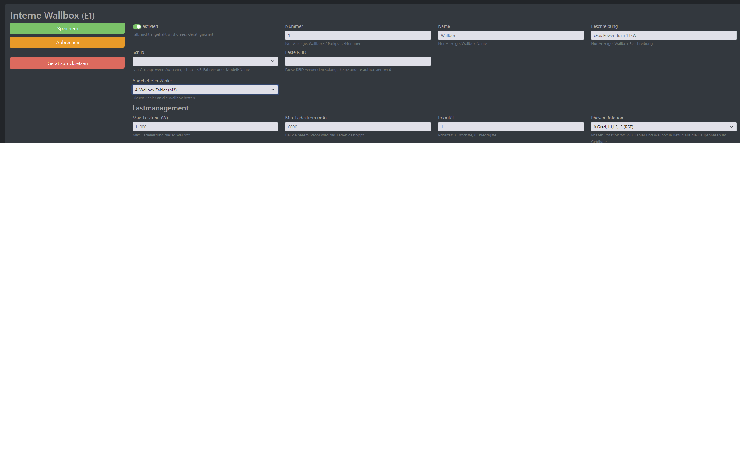
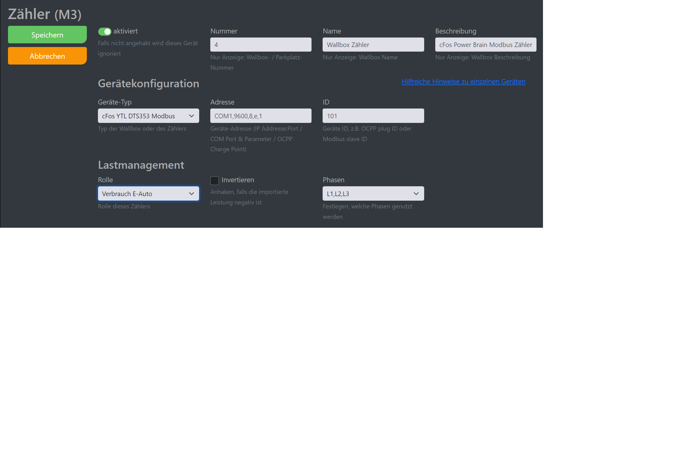
1. Master
In the Master EVSE (cFos Power Brain Wallbox), internal EVSE and the default cFos YTL Modbus meter 1 are already set up and activated as described above.
This Modbus meter is pinned. For the Charging Manager, it looks like the meter is built in. A tile for the meter in the overview window disappears.
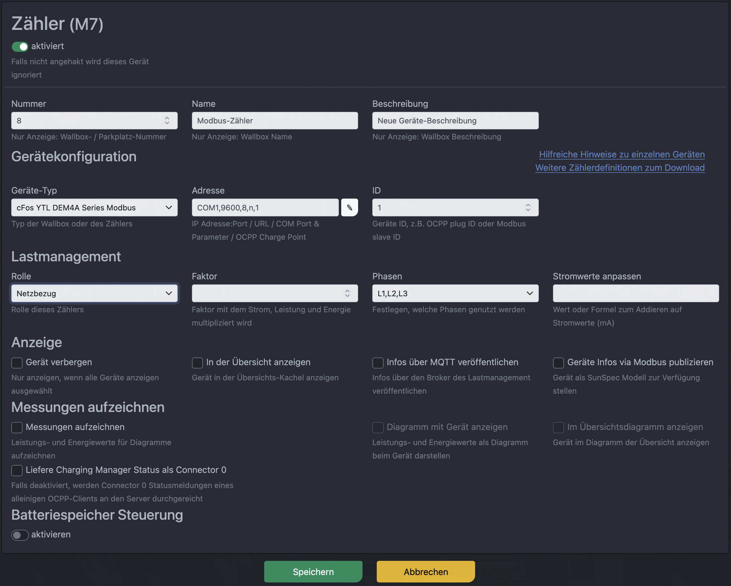
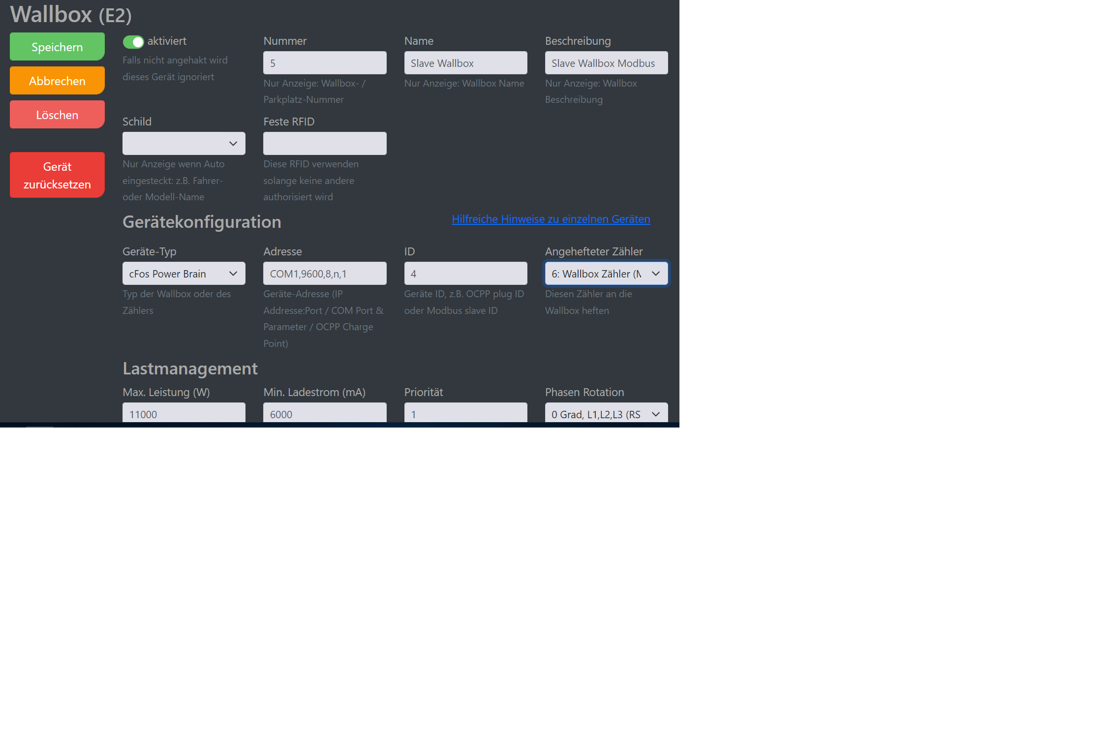
2. Slave
The 2nd EVSE (slave) is connected to the Modbus RTU with a twisted pair connection to the master EVSE. It is operated as a Modbus slave. As an example, the COM port parameters were entered as the address: COM1,9600,8,n,1 and ID is 4.
The slave is connected with phase rotation 120 degrees, i.e. the electrician has rotated the phases with respect to the master (L1 -> L2, L2 -> L3, L3 -> L1). This prevents one-sided phase loading when both cars are charging single-phase or two-phase. If both cars only charge in single phase, both can receive full power on their phase. The cFos Charging Manager can monitor this if it can measure individual phases (not measured here, but a phase rotation of 120 degrees has already been entered for demo purposes). The charging power is divided among the charging cars. If no meters are connected, the cFos Charging Manager assumes that the car always takes the power offered to it.
The same COM parameters must be entered in the slave.
2. Meter :
The second meter is also connected to the two-wire modbus and has the ID 102. It is attached to the second EVSE in the master. It cannot be attached in the slave, as the slave is not a Modbus master. Only the master EVSE may query other devices on the Modbus. The 2nd meter counts the consumption of the slave EVSE, so its role is "Consumption E-car". For the Charging Manager in the master EVSE, the slave EVSE looks like a EVSE with a built-in meter